Arduino DDS Sinewave Generator
Arduino Sine wave Generator using the direct digital synthesis Method
Here we describe how to generate sine waves with an Arduino board in a very accurate way. Almost no additional hardware is required. The frequency range reaches form zero to 16 KHz with a resolution of a millionth part of one Hertz! Distortions can be kept less than one percent on frequencies up to 3 KHz. This technique is not only useful for music and sound generation another range of application is test equipment or measurement instrumentation. Also in telecommunication the DDS Method is useful for instance in frequency of phase modulation (FSK PSK).
The DDS Method (digital direct synthesis)
To implement the DDS Method in software we need four components. An accumulator and a tuning word which are in our case just two long integer variables, a sinewave table as a list of numerical values of one sine period stored as constants, a digital analog converter which is provided by the PWM (analogWrite) unit, and a reference clock derived by a internal hardware timer in the atmega. To the accumulator , the tuning word is added, the most significant byte of the accu is taken as address of the sinetable where the value is fetched and outputted as analog value bye the PWM unit. The whole process is cycle timed by an interrupt process which acts as the reference clock. Further details of the DDS Method are described in web of course. This article published by Analog Devices is one of many good references.
MT-085: Fundamentals of Direct Digital Synthesis (DDS)
Software implementation
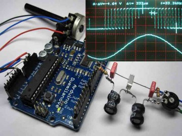
To run this software on an Arduino Diecimila or Duemilenove connect a potentiometer to +5Volt and Ground and the wiper to analog 0. The frequency appears on pin 11 where you can connect active speakers or an output filter described later.
/*
 *
 * DDS Sine Generator mit ATMEGS 168
 * Timer2 generates the  31250 KHz Clock Interrupt
 *
 * KHM 2009 /  Martin Nawrath
 * Kunsthochschule fuer Medien Koeln
 * Academy of Media Arts Cologne

 */

#include "avr/pgmspace.h"

// table of 256 sine values / one sine period / stored in flash memory
PROGMEM  prog_uchar sine256[]  = {
  127,130,133,136,139,143,146,149,152,155,158,161,164,167,170,173,176,178,181,184,187,190,192,195,198,200,203,205,208,210,212,215,217,219,221,223,225,227,229,231,233,234,236,238,239,240,
  242,243,244,245,247,248,249,249,250,251,252,252,253,253,253,254,254,254,254,254,254,254,253,253,253,252,252,251,250,249,249,248,247,245,244,243,242,240,239,238,236,234,233,231,229,227,225,223,
  221,219,217,215,212,210,208,205,203,200,198,195,192,190,187,184,181,178,176,173,170,167,164,161,158,155,152,149,146,143,139,136,133,130,127,124,121,118,115,111,108,105,102,99,96,93,90,87,84,81,78,
  76,73,70,67,64,62,59,56,54,51,49,46,44,42,39,37,35,33,31,29,27,25,23,21,20,18,16,15,14,12,11,10,9,7,6,5,5,4,3,2,2,1,1,1,0,0,0,0,0,0,0,1,1,1,2,2,3,4,5,5,6,7,9,10,11,12,14,15,16,18,20,21,23,25,27,29,31,
  33,35,37,39,42,44,46,49,51,54,56,59,62,64,67,70,73,76,78,81,84,87,90,93,96,99,102,105,108,111,115,118,121,124

};
#define cbi(sfr, bit) (_SFR_BYTE(sfr) &= ~_BV(bit))
#define sbi(sfr, bit) (_SFR_BYTE(sfr) |= _BV(bit))

int ledPin = 13;                 // LED pin 7
int testPin = 7;
int t2Pin = 6;
byte bb;

double dfreq;
// const double refclk=31372.549;  // =16MHz / 510
const double refclk=31376.6;      // measured

// variables used inside interrupt service declared as voilatile
volatile byte icnt;              // var inside interrupt
volatile byte icnt1;             // var inside interrupt
volatile byte c4ms;              // counter incremented all 4ms
volatile unsigned long phaccu;   // pahse accumulator
volatile unsigned long tword_m;  // dds tuning word m

void setup()
{
  pinMode(ledPin, OUTPUT);      // sets the digital pin as output
  Serial.begin(115200);        // connect to the serial port
  Serial.println("DDS Test");

  pinMode(6, OUTPUT);      // sets the digital pin as output
  pinMode(7, OUTPUT);      // sets the digital pin as output
  pinMode(11, OUTPUT);     // pin11= PWM  output / frequency output

  Setup_timer2();

  // disable interrupts to avoid timing distortion
  cbi (TIMSK0,TOIE0);              // disable Timer0 !!! delay() is now not available
  sbi (TIMSK2,TOIE2);              // enable Timer2 Interrupt

  dfreq=1000.0;                    // initial output frequency = 1000.o Hz
  tword_m=pow(2,32)*dfreq/refclk;  // calulate DDS new tuning word

}
void loop()
{
  while(1) {
     if (c4ms > 250) {                 // timer / wait fou a full second
      c4ms=0;
      dfreq=analogRead(0);             // read Poti on analog pin 0 to adjust output frequency from 0..1023 Hz

      cbi (TIMSK2,TOIE2);              // disble Timer2 Interrupt
      tword_m=pow(2,32)*dfreq/refclk;  // calulate DDS new tuning word
      sbi (TIMSK2,TOIE2);              // enable Timer2 Interrupt

      Serial.print(dfreq);
      Serial.print("  ");
      Serial.println(tword_m);
    }

   sbi(PORTD,6); // Test / set PORTD,7 high to observe timing with a scope
   cbi(PORTD,6); // Test /reset PORTD,7 high to observe timing with a scope
  }
 }
//******************************************************************
// timer2 setup
// set prscaler to 1, PWM mode to phase correct PWM,  16000000/510 = 31372.55 Hz clock
void Setup_timer2() {

// Timer2 Clock Prescaler to : 1
  sbi (TCCR2B, CS20);
  cbi (TCCR2B, CS21);
  cbi (TCCR2B, CS22);

  // Timer2 PWM Mode set to Phase Correct PWM
  cbi (TCCR2A, COM2A0);  // clear Compare Match
  sbi (TCCR2A, COM2A1);

  sbi (TCCR2A, WGM20);  // Mode 1  / Phase Correct PWM
  cbi (TCCR2A, WGM21);
  cbi (TCCR2B, WGM22);
}

//******************************************************************
// Timer2 Interrupt Service at 31372,550 KHz = 32uSec
// this is the timebase REFCLOCK for the DDS generator
// FOUT = (M (REFCLK)) / (2 exp 32)
// runtime : 8 microseconds ( inclusive push and pop)
ISR(TIMER2_OVF_vect) {

  sbi(PORTD,7);          // Test / set PORTD,7 high to observe timing with a oscope

  phaccu=phaccu+tword_m; // soft DDS, phase accu with 32 bits
  icnt=phaccu >> 24;     // use upper 8 bits for phase accu as frequency information
                         // read value fron ROM sine table and send to PWM DAC
  OCR2A=pgm_read_byte_near(sine256 + icnt);

  if(icnt1++ == 125) {  // increment variable c4ms all 4 milliseconds
    c4ms++;
    icnt1=0;
   }

 cbi(PORTD,7);            // reset PORTD,7
}
Results
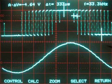
In the upper part of the picture you see PWM signal on pin 11 and in the lower part what the filter makes out of it. The sinewave looks not so clean but thats mainly the limited resolution of the digital oscilloscope.
The spectrogram shows a surprisingly good result. The big peak is the output frequency of about 1000 Hz. All unwanted distortions are below 50 dB which is roughly what we expect from a signal what is generated by an 8-bit DAC. ( 1/256 = 48dB).
DDS Spreadsheet
dds_calc A little worksheet around the DDS formula to calculate the tuning word.
PWM Output lowpass Filter
For a start you can just connect the output pin 11 to active speakers. But usually you need lowpass filter is to get rid of the 32KHz sampling frequency in the output signal. A Chebyshef lowpass with a cutoff at 12 KHz build with standard component values is shown here.
PWM DDS dedicated Hardware
This software implementation of DDS has of course several drawbacks in case of signal purity and frequency range due to the limited speed of the software algorithm and analog capabilities of the atmega chip. DDS modules which are using dedicated DDS chips are the state of the art in signal generation and offer a frequency coverage from zero up into the 100MHz range.
WSPR Application
WSPR “Weak Signal Propagation Reporter” pronounced Whisper is a system which reports the propagation of very weak radio signals over the world. The DDS Method was used here to generate a tone sequence where four frequencies (1497,8 1499,3 1500,7 1502,2 Hz) are used code a message in a very robust manner. This message is transmitted with a low power radio beacon and can be observed worldwide via wspr.net .
Forum
Further questions to this topic can be discussed here:
Arduino Forum :: Using Arduino :: Audio :: Arduino DDS Sinewave Generator
http://arduino.cc/forum/index.php/topic,64217.0.html
Contact
Martin Nawrath, nawrath@khm.de


