So I have a bit of a new mini-project: I have decided to turn my attention to adding (limited) μ-(microprocessor)-control of my radio to the list of things I am working on.
This whole idea stemmed from my desire to make a one-off microprocessor all-in-one satellite tracking and Doppler tuning apparatus. Essentially, a dedicated microprocessor would track a selected satellite and then tune the radio’s downlink frequency to match the Doppler shift during the pass. All of this can be done via some Kepplerian elements stored on an SD-card and some moderately sophisticated calculations.
Due to the sad state of amateur satellites (in my humble opinion), I have decided not to pursue the tracker functionality (for now).
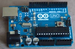
Having already done some research on the Doppler tuning portion of the project, I was well aware of what could be done with an Arduino board (I am too lazy to solder a purpose-built board), CAT (computer) control protocols, and the microphone jack of a Yaesu FT-857D radio.
Yes I could have done the easy thing and decided to use the CAT jack on the rear of the FT-857D but what fun is that? Honestly though, I wanted to keep that port clear for other uses (such as a tuner which may not have a CAT-port pass-thru). While browsing the various Yaesu FT-8*7 manuals, I noticed a little gem on page #60 (PDF page #62) of the FT-897D (not 857!) manual. Also, browsing the function menus (specifically selection #59) indicated:
“MENU MODE No•059 [MIC SEL]“
So long as you do not plan to use the mic, it is possible to pass CAT protocol data to the radio through the microphone port (ie. digital modes!) if you select: CAT in the MIC SEL menu.
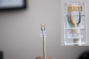
To make the appropriate cable, I took a piece of 2-pair telephone cable and connected the RX, TX and GND pins to an RJ45 connector. In the photo, you will also see the yellow conductor connected in the RJ45 plug. This is NOT necessary for the CAT connection, and it will be unused in this example.
The green conductor (let us call it RJ45 pin 1) is connected the RX port of the Arduino (normally that would be pin-0) and the red conductor (RJ45 pin 2) is connected to the TX port (normally, pin-1) while the black conductor (RJ45 pin 7) is connected to any available ground (GND) on the Arduino.
To control the radio, various commands may be issued to the radio using a variant of the Yaesu CAT control protocol. After packet sniffing the serial data, I learned many of the codes which I later found in the FT-897D manual on page #64 (PDF page #66). The commands must be issued as a five-byte serial data packet. As an example, to change the frequency of the radio to 144.390MHz for APRS work, you would issue the command as:
14 43 90 00 01 (the 01 is a “command” byte)
In the standard Arduino development environment, I store the command in a byte array:
// set constant variable to the N.A. APRS frequency of 144.390MHz
const byte aprs[5] = {0x14,0x43,0x90,0x00,0x01};
and then issue that command to a software-based serial port (named rigCat) as follows:
for (byte i=0; i<5; i++) {
 rigCat.write(aprs[i]);
}
which then tunes the radio to 144.390MHz as desired.
Initially, everything was working just fine as it was connected since the FT-857D CAT uses TTL level logic (+5V) and the Arduino is compatible with these levels. Not long after I had some success, the setup stopped working. Now I am in the troubleshooting stages. With 10-hour days at work, I am only interested in short-duration project sprees at the moment. I’ll post updates to the project as I solve the μ-control interface issues.


