Stepper Motor drive from Arduino
Stepper Motor drive from Arduino
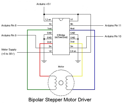
In this tutorial we will show you how to connect a bipolar stepper motor to an Arduino Uno board. The stepper motor we are using is the Sparkfun Stepper Motor but you can use any other 4-wire bipolar stepper motor.
Because a stepper motor draws a higher current than the Arduino processor can handle we are going to use a Quad half H-Bridge chip to control the stepper motor. The popular Texas Instruments SN754410 chip is ideal for this.
The Arduino Stepper library will work directly with this chip without any code modifications, so it is just a simple matter of wiring it up as per the diagram below.
Once all wired up, load one of the example stepper motor sketches. The One-Revolution sketch is shown below which turns the stepper motor one revolution in one direction, then one revolution in the other direction.
/*
 Stepper Motor Control - one revolution


 This program drives a unipolar or bipolar stepper motor.
 The motor is attached to digital pins 8 - 11 of the Arduino.


 The motor should revolve one revolution in one direction, then
 one revolution in the other direction.


 Created 11 Mar. 2007
 Modified 30 Nov. 2009
 by Tom Igoe


 */

#include <Stepper.h>

const int stepsPerRevolution = 200;  // change this to fit the number of steps per revolution
                                     // for your motor

// initialize the stepper library on pins 8 through 11:
Stepper myStepper(stepsPerRevolution, 8,9,10,11);

void setup() {

  // set the speed at 60 rpm:
  myStepper.setSpeed(60);
  // initialize the serial port:
  Serial.begin(9600);
}

void loop() {
  // step one revolution  in one direction:

   Serial.println("clockwise");
  myStepper.step(stepsPerRevolution);
  delay(500);

   // step one revolution in the other direction:
  Serial.println("counterclockwise");

  myStepper.step(-stepsPerRevolution);
  delay(500);
}
SN754410 Quad Half H-Bridge
Faster, cheaper, smaller, better, right? The SN754410 Quad Half H-Bridge is just that. Capable of driving high voltage motors using TTL 5V logic levels, the SN754410 can drive 4.5V up to 36V at 1A continuous output current!
For even higher current applications, it is possible to physically stack two devices on top of each other to get almost 2 A of drive current.
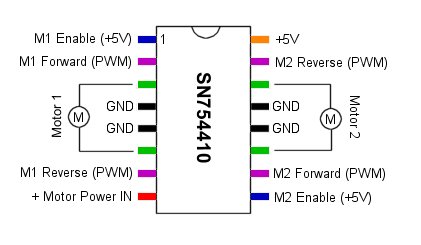
The SN754410 is a quad half H-bridge IC. This allows the chip to either control 4 motors in one direction using the 4 half H-bridges or to control 2 motors in both directions using a full H-bridge for each motor.
The following shows the connections for controlling 2 motors in either direction using 2 full H-bridges.
Pin Name H-Bridge Function Notes 1 1,2EN Motor 1 Enable Setting this pint o 0V (LOW) will turn off the motor, setting it to 5V (HIGH) will enable the motor. Connect this pin to the 5V supply, or use as an emergency shutoff. 2 1A Motor 1 Forward Set this pin to 5V (HIGH) to turn Motor1 in one direction. Motor Speed can be controlled by using PWM into this pin 3 1Y Motor 1 Power Connect to one pin of Motor1 4 Ground Ground Connect to ground - required for heat sinking 5 Ground Ground Connect to ground - required for heat sinking 6 2Y Motor 1 Power Connect to other pin of Motor1 7 2A Motor 1 Reverse Set this pin to 5V (HIGH) to turn Motor1 in the opposite direction. Motor Speed can be controlled by using PWM into this pin 8 VCC2 Motor Power Source Positive power source for your motors. (i.e. connect to battery - max 36V) 9 3,4EN Motor 2 Enable Setting this pint o 0V (LOW) will turn off the motor, setting it to 5V (HIGH) will enable the motor. Connect this pin to the 5V supply, or use as an emergency shutoff. 10 3A Motor 2 Forward Set this pin to 5V (HIGH) to turn Motor2 in one direction. Motor Speed can be controlled by using PWM into this pin 11 3Y Motor 2 Power Connect to one pin of Motor2 12 Ground Ground Connect to ground - required for heat sinking 13 Ground Ground Connect to ground - required for heat sinking 14 4Y Motor 2 Power Connect to other pin of Motor2 15 4A Motor 2 Reverse Set this pin to 5V (HIGH) to turn Motor2 in the opposite direction. Motor Speed can be controlled by using PWM into this pin 16 VCC1 IC Logic Power Regulated +5V (VCC / VDD)
Documents: SN754410 Datasheet