I have been experimenting with small (generally less then 1/10 wavelength circumference) transmitting loop antennas in the HF bands since about 1988. I find them very useful when space for a full size antenna is limited. When care is taken during the construction to minimize resistive losses, performance can be very respectable. If an antenna can only be mounted very close to the ground, a small loop (when mounted vertically) will very likely out perform most other antennas due to their independence from lossy ground return currents and their near hemispheric radiation pattern. This is not to say that a small loop doesn't have extra losses when mounted near the ground, but since most of the near-field energy is stored in the magnetic field rather then in the electric field, dielectric losses are minimized. Another advantage is that the sharp nulls in the azimuth pattern of a vertical loop can be used to null out local EMI/RFI.
I have a more technical description of small transmitting loops further down on this page.
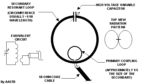
Construction of a small loop is pretty straight forward. Simply choose the desired loop diameter based upon materials available and performance desired. The larger the loop diameter, the greater the efficiency. If it is made larger then about 1/10 wavelength in circumference it will no longer be classified a small loop and it's radiation pattern will begin to change. You may not care about this. Choose a conductor with as large diameter as you can find and it preferably should be copper (or silver). This is to keep the resistive losses low. The conductor does not have to be solid. An often thought of idea is to use the braided shield of coax cable but be cautious if you do this because I once used a braided conductor to connect from the main loop to the tuning capacitor and the braid actually got hot! I'll leave that problem for the physicists to figure out. For a quick loop one time though I used some 3/8" Heliax coax for the main loop and had good results. Heliax cable uses a corrugated copper for the shield.
Choose a capacitor value that will resonate the loop to the desired frequencies of operation. The capacitor is the most difficult part of constructing this type of antenna. Because of the very high Q, most available capacitors will start arcing over at powers as low as 10 watts. Remember that even with only a few watts of power, there can be thousands of volts across the capacitor and several amps of current through the capacitor (not necessarily in phase, no free power!). Losses in convientional capacitors can be high due to the several milliohms of resistance found in thier brush contacts and non-welded vanes. For this reason you should try and find or build a split stator capacitor of some sort with welded vanes. The idea is to not have RF current flowing through any moving and/or mechanical contacts. Plate spacings will have to be large high except for very low powers. If you are using QRP power levels and all you can find is a single stator/rotor capacitor don't hesitate to use it though. Just be aware that the losses will most in likely be greater. I have made antennas using convientional broadcast receiver capacitors and they worked good for QRP use although I know performance could have been much greater. Some folks have built "trombone" style capacitors out of copper tubing for low loss/high power performance. Some form of reduction drive is highly recommended due to the very sharp tuning of the antenna. Also, if used outdoors for long periods of time you will want to protect the capacitor from water and insects.
To couple energy into the loop several methods are available. By far, the easiest method is to simply construct a coupling loop as indicated in the sketch. No physical connection is required between this coupling loop and the main loop although no harm will come if you want to connect the bottom shield of the coupling loop to the bottom of the main loop for some reason. For electrostatic shielding properties, you may want to construct a shield coupling loop. This can be done by simply taking the end of the feedline coax and loop it back upon itself to form the desired loop dimensions. Where the loose end meets the coax again, strip and solder both conductors of the loose end to the shield of the coax. At the top of this coax loop, cut the shield and produce a small gap all the way around the coax. The shield should be totally seperated at this point. This style of shielded coupling loop will make the entire antenna system unresponsive to electric fields. If the small coupling loop is made slightly larger than is necessary then one can adjust the coupling by rotating the small loop inside the larger loop. This makes for a very precise method of adjusting the coupling. Another method of coupling to the main loop is via a autotranformer style coupling. With this method, the shield of the coax is connected to the bottom of the main loop an the center conductor of the coax is connected to the main loop several inches from the shield connection. This connection point will have to found experimentally and doesn't lend itself to easy adjustment but it will work just find electrically. This method resembles the "gamma" style match of Yagi-Uda arrays without the series capacitor. There are also capacitive methods to couple to the main loop using a capacitive voltage divider technique that look rather difficult to me so therefore I have no experience with it. Your on your own here. Whatever method you choose to couple the feedline to the antenna the coupling should be adjusted for the lowest SWR at resonance somewhere near the center of the antenna's designed frequency coverage. Once the coupling is adjusted no further adjustments will be required throughout this range. This is yet another beauty of this type of antenna.
I hope you find the following program that I wrote to help me in the design of these antennas useful. Please note that where the program calls for a resistance loss in milliohms that this is only if you want to estimate additional sources of loss such as that from poor connections. The program assumes a copper conductor and the resistance for a copper conductor is already accounted for. Also note that the program will inform you of a maximum loop diameter for the loop that will give you the so called small loop performance. If the diameter of the loop is increased beyond this value the efficiency will increase but the pattern will change. The extreme example of this would be if you were to increase the size to a full wavelength. The efficiency would be very high and the pattern (broadside pattern) would be opposite that of a small loop.
This loop is 3 feet in diameter and is constructed of 5/8" copper pipe. I'm using 2 sections of a three section variable capacitor. One side of the loop is connected to one stator and the other side of the loop is connected to the other stator. This is equivalent to two capacitors in series with the rotor being common to both. With this arrangement no current flows through the lossy brush contacts. A electrostatically shielded coupling loop is used to feed the antenna.


This loop has performed very well for me. It will tune from about 9 MHz to 28.5 MHz.
In August of 2002 I performed an experiment to compare the performance of this loop antenna to that have a full size halfwave dipole antenna at the same height. You can review this experiment here:
I started experimenting with small loop antennas around 1988 and I had no data except for photos of military loop antennas I had seen in the Jane's catalog. My first attempts were trial and error but I had pretty good success. Below are some photos from August 8, 1991of one of my first successful loop antennas. It tuned from 4.8 MHz to 17.5 MHz and I used it for a number of years. It was constructed from 3/4 inch copper tubing and was fed using autotransformer type of coupling. This means of coupling resembles a "gamma" match but without the series capacitor. The main tuning capacitor was a 500 pF air variable.


The main problem that I've always had with magnetic loop antennas is that they are not very easy to transport in the field. I've always wanted something that I could fold up and take with me to the field and then deploy at a campsite. Unfortunately, portability and efficiency are difficult to be had at the same time when we're dealing with small loops. Any kind of flexible joint usually has enough resistance to seriously effect the antenna's efficiency.
Recently I've been playing around with a couple of prototypes that are both tuned to 30m. The first loop is made from RG-8 coax and despite previous experiments with high power that indicated to me that braid was not a good idea for low radiation resistance antennas I chose to do so anyway for the sake of portability. The antenna is square and in the first experiment I supported the loop with rope and sticks inside my house. This was also the first time that I fed a small loop with a small ferrite coupling transformer. I used the coax itself as the capacitor. With my antenna analyzer I was quickly able to tune the loop to the middle of 30m by trimming the coax.


With my transmitter set to 5 watts output I promptly made several successful QSO's.
On the next nice day I took the antenna outside to do some further experimentation. The antenna performed very nicely although I don't have any quantitative data on it yet. When I get some more time I'll put more details on the Web so that it can be easily constructed but for now take a look at the photos below.


Later, I decided to develop a loop that could be hung from a single support and be folded up to carry in a small backpack or sack. I used 22 AWG solid insulated copper wire that was left over from a garage door opener I had installed and constructed it as a delta loop. Since I knew the efficiency would be low I made the loop larger then normal to make up for it. For the capacitor I constructed a "gimmick" capacitor by leaving the end of the wire together. Once again I trimmed the capacitor until I was close to the design frequency. I simply split the ends and moved them around to fine tune the antenna to the exact frequency. Initially, I just cut a length of the parallel wire to the desired circumference and then split the wire up to the "gimmick" capacitor. Then I installed the ferrite toroid and soldered the ends together.
Even though I'm sure that the efficiency of this antenna is relatively low I had a nice 30 minute QSO with it at 5 watts just before these photos were taken. Once again I hope to have more details available soon. Here is a hint: The higher the impedance of the loop (larger loop), the more turns that are needed on the primary (red wire) to obtain a 1:1 VSWR at the resonant frequency.


Below is a small (3" dia.) electrostatically shielded loop antenna that I developed for two meters. It is constructed of semi-rigid coax (solid copper shield) and the small coupling loop can turn inside the main loop. I really only built this loop for demonstration purposes but it does work. The bandwidth is only about 100-200 kHz (at 146 MHz) but it does work at least as good if not better then a standard "rubber duck" antenna. The two sharp nulls in the plane of the loop are very pronounced and can be used for direction finding purposes.

Here are some photos of a very high efficiency loop built by JL1BOH for mobile use! He really know what he is doing. I thank him for sending me the good photos.


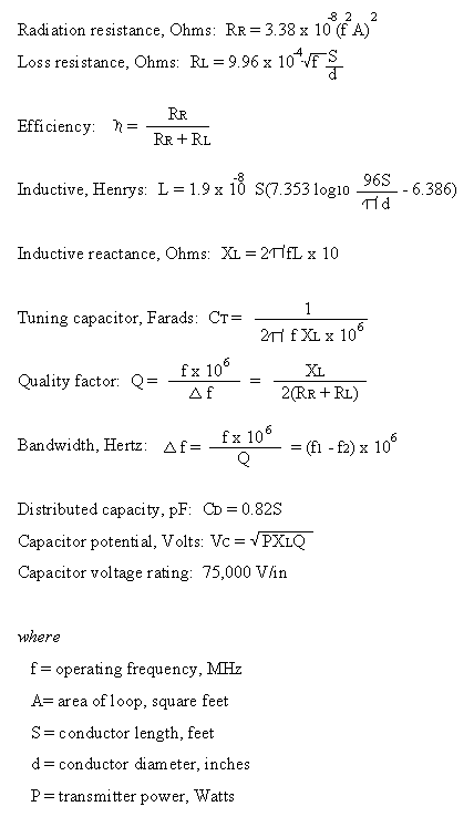
Below in the table is an example of some computed data on a 3 foot diameter loop antenna.
Notice the results when some resistance is added. This just goes to show that if additional resistive losses are expected in a given design (such as a capacitor with brushes), there may not be any advantage to going to larger conductors - a small conductor will work just as bad! Several people have had good results though with just such antennas . Remember that the loss indicated is the loss relative to a perfect antenna and does not take into account ground reflection/pattern gain, etc. Even with a calculated loss the field strength for a particular skywave path may be greater than that of a more efficient antenna of different design. This is because of the near hemispherical radiation pattern in the elevation pattern of a small loop. In other words, try it anyway. You may like the results!
A small loop antenna is basically just a very large parallel tuned circuit or tank circuit. The loop can be veiwed as a large single turn loop of this circuit. Due to the large (relatively speaking) size of this inductor, radiation very easily takes place. The more turns there are to this inductor, the less radiation there is. For some low frequency loop antennas several turns may be required to obtain resonance but radiation efficiency usually suffers. Taken to the extreme, ordinary tank circuits don't radiate much at all due to the small, multiturn inductors.
Coupling to this tank circuit is easily accomplished by transformer coupling (see the above sketch) or by autotransformer coupling by means of a tap up the conductor (as described earlier). Almost all antennas can be reduced to similiar type descriptions. They are simply very efficient transformers that couple energy from the feedline impedance to the impedance of free space (~377 ohms).
There are a lot of misconceptions about small loop antennas. Small loop antennas are often referred to as magnetic antennas. This is because they mostly respond to the magnetic component of an electromagnetic wave and transmit a large magnetic component in the near field. In the far field (>1 wavelength distance*) the RF from a small loop is the same as that from any other antenna, electromagnetic. It is often believed that magnetic antennas will not respond to local noise because local noise is mostly electrostatic. This is ONLY true if the offending source is in the near field of the loop antenna AND if the source is truly of electrostatic origin. An example of this would be a high impedance power transmission line that had an arcing insulator and was right next to the antenna. In this case a small loop would not respond to the interference as much as say a dipole would. The same can not be said if the offending transmission line was miles away. This is because you cannot have a time varying electric field without generating a time varying magnetic field and vise versa. This is what an electromagnetic wave (RF) is. It is worthy to note though that due to the two sharp nulls in the small loop's radiation pattern it is very easy to null out local interference while still obtaining large azimuth coverage area. Also, unless the loop contains an electrostatic shield it will most likely respond to very close electric fields due to capacitive coupling.
I believe that reason small loop antennas perform so well at very low heights is because in the near field most of the loop's field component is magnetic and magnetic losses in ordinary ground are much less then the dielectric losses that most antennas with a large electric field component are subject to. Also, when mounted vertically small loops have a radiation pattern that changes very little with height. Many authors (such as ON4UN) say that a vertical small loop does not suffer from the pseudo-Brewster angle notch-out effect that other vertical antennas will have when installed over real ground. This is a difficult thing to understand since this is a far field effect and at that distance the EM wave is just like that from any other antenna. Experience would indicate that this effect may indeed be true however. Determining the actual polarization of this antenna can be rather difficult. Polarization is determined by the orientation of the E-field. The E-field is almost totally across the tuning capacitor on a small loop that is 1/10 of a wavelength in circumference or less. Therefore, the polarization is in line with the capacitor. When the loop is mounted vertically with the tuning capacitor on top the polarization is horizontal. That is, when viewed from the side. Of course the null is pointed to the side so not much radiation occurrs there. When viewed from the end at any elevation other then 0 degrees the polarization will appear to be vertical. With a horizontal loop the polarization will be horizontal. The main difference is the orientation of the antenna pattern null and the E-field losses would conceivably be greater for a horizontal loop the is close to the ground. Some literature I've read suggest that the pattern for a horizontally mounted small loop will have a lower take off angle then other horizontal antennas. I've seen no justification for this claim except that there will always be a null straight up (broadside) due to the nature of a small loop antenna's free space pattern and this will cause the main lobes to be lower then that, say of a low dipole that has the main lobe straight up. This can be viewed like a low dipole elevation pattern (a wide lobe straight up) with a notch taken out at 90 degrees. There may be some elevation angle difference due to the fact that it is primarily the magnetic field interacting with the ground in the newar field rather then the electric field. As the height is increased I would expect this difference to gradually dissappear. Since most of the near field component is magnetic the antenna should be placed far from ferrous objects, such as steel towers, iron framework, etc. Ordinary copper house wire may or may not be a loss factor depending on resonances in the wiring, loop areas, etc. I have had good luck using small loops indoors however.
