Antennas
By David Jefferies

Antennas
By David Jefferies
What is a loop antenna?
![]() loop antenna
has a continuous conducting path leading from one conductor of a two-wire transmission
line to the other conductor. You may think of it as a "coil that radiates". The
coil may have only a single turn. It may have arbitrary shaped perimeter, but the essence
of a coil is that the defining wire encloses an area. Thus, a folded dipole is not a loop
antenna in this sense, since the area inside the conductor path is vanishingly small.
loop antenna
has a continuous conducting path leading from one conductor of a two-wire transmission
line to the other conductor. You may think of it as a "coil that radiates". The
coil may have only a single turn. It may have arbitrary shaped perimeter, but the essence
of a coil is that the defining wire encloses an area. Thus, a folded dipole is not a loop
antenna in this sense, since the area inside the conductor path is vanishingly small.
Symmetric loop antennas have a plane of symmetry running along the feed and through the loop. Planar loop antennas lie in a single plane which also contains the conductors of the feed.
Three-dimensional loop antennas have wire which runs in all of the x,y, and z directions (in a rectangular Cartesian system). By definition they are not planar. They may, however, be symmetric about planes which contain the feed.
It is possible for the loop antenna plane not to contain the run of the feed. This matters for situations where the feed currents are not perfectly balanced.
What size is a loop antenna?
There are at least two distances which define the "notion of size" in a loop
antenna. These are, the total length of wire between the "go" and
"return" of the feed, and the largest distance from one point on the loop
conductor to another, measured in a straight line (as light would propagate). One might
also think of another distance that "matters", namely the distance from the feed
junction with the loop, to the most remote point on the loop conductor. All these
distances need to be thought of in units of a wavelength at the carrier frequency handled
by the antenna.
Loops and probes in waveguide
If one wants to couple radiation from a two-wire feed (possibly coax) to a waveguide, one
commonly does this by means of a probe (which couples to the electric field in the guide,
and is the equivalent of a monopole) or by means of a loop (which couples to the magnetic
field in the guide; the maximum of magnetic field lines pass through the loop). Waveguide
may be regarded as a microcosm of the great outside world.
Phase delay across a loop
Critical to the functioning of any loop antenna is the concept of the "phase
delay" that occurs for em radiation to get from one point on the loop to another,
some distance away. In the case of vanishingly small loops, the traditional calculation
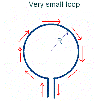
assumes that the current is the same everywhere around the loop perimeter,

as can be seen diagrammatically in this figure. In this case, the radiation along any loop diameter arrives from an oppositely directed but parallel element of current after a short time delay, which puts in a phase shift so that the radiation contributions do not entirely cancel.
 This traditional argument quickly leads to the result that the radiation resistance of a
small circular loop rises as the (ratio of loop diameter to wavelength) raised to the
fourth power. A small increase in loop diameter therefore results in a greatly increased
radiation resistance.
Just as with a small rod antenna, where the radiation resistance rises as the square of the length of the exposed radiating wire (see radimp.html), so also in a loop antenna the radiation resistance, were it not for the cancellation effects, might be expected to rise as the square of the circumference, and therefore as the square of the loop radius or diameter in the case of a small circular loop. However, there are additional cancellation effects, and this puts in an additional factor proportional to the square of the diameter, radius, or circumference.
One of the most significant attributes of a loop antenna is that "go" current in one part of the loop is offset by "return" current in another. It is only because these go and return paths are physically separated in space that a small loop antenna can radiate at all. Otherwise the radiation from one little current element would exactly cancel that from the other. In fact, this does happen for radiation directions normal to the plane of a vanishingly small planar loop. In such directions there is a deep radiation null.
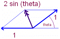
Quantitatively, for a circular loop of radius R, when R/lambda = 0.25, the diameter is half a wavelength and the 180 degree phase shift, for the radiation to get from the "go" current at one end of the diameter to the oppositely-directed "return" current at the other end of the diameter, results in an enhancement factor of 2 over the radiation from just a single current element. The radiation from one element arrives "in phase" with the contribution from the other element, half a wavelength away but opposite in sign. The perimeter is then (2 pi 0.25) wavelengths which is 1.57 wavelengths and so the assumption of constant current around the loop perimeter has broken down.
For R/lambda = 1/100 or 0.01, the field contributions nearly cancel. The expression for the "enhancement factor" is [2 sin(2 pi R/lambda)] which then evaluates to 0.126 very nearly. This is a lot less (1/16th) than that due to the quarter-wave radius loop (enhancement of 2) and will make (1/16)^2 = 1/256 difference to the contribution of these little elements to the radiated power and to the radiation resistance.
For R/lambda = 1/50 (or 0.02), the enhancement factor is 0.25, and for R/lambda = 1/20 (or 0.05) the enhancement factor is 0.61 and at this point the perimeter has got to 0.3142 of a wavelength.
Non-uniform currents
Of course, in certain loop structures the size of the currents in different elements of
length along the loop wire will vary. Thus, loop antennas which have a total wire length
approaching or exceeding an appreciable fraction of a wavelength can be efficient
radiators with radiation resistance that approaches a match to common feed-line
impedances. It is only in vanishingly small loop antennas that we are justified in
assuming that the current is the same at every point along the loop wire. In intermediate
cases, this may sometimes be a justifiable approximation, but certain textbooks which
treat a circular loop antenna of radius lambda/25 (which has a loop wire length of about
lambda/4) as if the approximation were sufficiently valid, may be in serious error. It is
partly for this reason that there is some controversy about the radiation resistance of
intermediate-sized loop antennas.
The folded-dipole approximation
For a loop where the perimeter is about a whole wavelength, the folded dipole analogy may
be better. We imagine the loop as being formed from a "bulged-out" folded
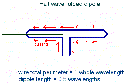
half-wave dipole for which the current distribution looks like this :-

The current in the element of wire diametrically opposite the feed is now directed from right to left, rather than from left to right as it would be in the vanishingly small loop. The currents up and down in the elements on the horizontal diameter have vanished, and it is for this reason that there is no radiation from this scenario in the plane of the loop in the horizontal direction.
The radiation resistance of this mode is quite high because the cancellation between currents on opposite ends of a diameter is no longer so complete. For a circular loop of perimeter one wavelength, the radius is 1/(2 pi) wavelengths, or about 0.16 wavelengths. We are still talking about a physically small-sized loop therefore. For example, at a wavelength of 20 metres such a loop would have a diameter of 6.4 metres and would be an effective wideband radiator.
The quarter-wave shorted line approximation
 Now
consider a loop which has a perimeter of just one half of a wavelength. At 20 metres
wavelength this would be a loop of diameter 3.2 metres. We may consider a bulged-out
length of transmission line having the same total wire length. A little thought shows that
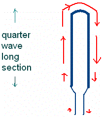
the transmission line model is a short circuited quarter-wave section of line. The input
current is zero in the parallel line approximation, as the line presents an open circuit
to the generator. Of course, this will not be exactly true when we have "bulged
out" the line section; for one thing, the short circuit point will have moved
physically closer to the feed.
What is clear, however, is that in this approximation the current in the element diametrically opposite the feed runs from left to right, not from right to left as it did in the folded dipole example. It is also going to be significantly larger than the current supplied by the feed.
As we increase the perimeter of the loop from a quarter wavelength to a half wavelength, there must therefore be a region where the current opposite the feed is smaller than the feed current, and indeed it must at some point pass through zero. Thus it is apparent that for all intermediate loops of diameter greater than 0.16 wavelength, the "small loop" approximation is not valid, and very significant radiation occurs. The Q will be reasonably low and the bandwidth and radiation resistance will have usefully large values. Those people with simulation packages may like to quantify these "general statements".
Phase shifts in the current distribution
Now, it is known that the radiation resistance for a small loop antenna is often swamped
by the loss resistance due to the current being confined to a small skin depth of
conductor at the wire or tube surface. Thus we have to consider phase shifts between
oppositely-directed currents on opposite ends of a loop diameter (for the special case of
a circular loop) brought about by the distributed inductance, resistance, and capacitance
of the loop line. Loop radiation is often (usually) measured with the loop mounted in a
vertical plane, and one goes away a significant distance on a flat ground so that the
radiation is measured on a horizontal (level) path in the plane of the loop. It is easy to
see that for a symmetric loop (as discussed above) the current elements contributing to
the radiation, up and down on opposite sides of the loop, have balanced amplitudes and
phases. Thus we expect the traditional formula for the radiation from a vanishingly small
loop to be approximately correct for intermediate loops, in this scenario of horizontal
path radiation. For those loops of this kind of size where radiated field strengths have
been measured and reported, it is said that this was the measurement geometry.
For other directions of the diameters of the loop, which are at a slant (intermediate between horizontal and vertical) angle to the ground, there will be phase shifts and amplitude differences between the little elements of current flow at the ends of this diameter. As stated, these phase shifts are due to the combined effects of distributed series inductance and shunt capacitance, and series skin-effect loss resistance. However, for loops where the phase shifts have a significant effect, the total wire perimeter will probably be long enough so that the amplitudes of the current elements change as well, and this will also generate a contribution to the radiation.
Quantifying these phase and amplitude shifts would appear to be quite a difficult problem. In terms of the current flow through a continuous conductor having distributed inductance and resistance per unit length, Kirchoff's current law indicates that the current is the same everywhere and that there are no phase shifts. However, if we then allow for the shunt capacitance, between elements of the loop tube or wire (which has non-vanishing surface area), then the phasing of current flow around the loop becomes a function of the loop wire diameter (or tube diameter) as well as the skin depth loss. A simulation might sort out some of these issues, but as it would return global values for the antenna properties, the local behaviour might not be transparent.
It is not unreasonable to expect, therefore, that intermediate-sized loops will radiate more strongly along such slant diameters than the traditional theory might predict. This effect is expected to be quite small, overall. For, the cancellation of the oppositely-directed current elements is no longer so complete: they have differing amplitudes and phases. This will put up the radiation resistance of the loop. Paradoxically, therefore, the presence of loss resistance in the loop due to joule heating in the skin depth where the current flows, may enhance the total radiation over what it would be for a lossless conductor having the same geometry.
The loop (intermediate size) will therefore radiate up and down preferentially. If we mount the loop with its plane horizontal, it should be possible to check on this effect by moving around the loop at constant range, measuring the fields radiated as we go. The prediction is that there will be some anisotropy in the radiation, symmetrically disposed with reference to the feed axis.
For the case of non-constant amplitudes and phases, there will also be radiation normal to the plane of the loop. This forms the basis of a simple and sensitive experimental method of deciding whether a loop antenna is functionally "small", or in the "intermediate size" range. In the case of a truly "small" antenna, there should be a very deep null in the far field region at directions on the axis of rotation of the loop. This null progressively fills in as one makes the loop diameter larger. By the time the loop diameter is about lambda/10 there should be appreciable radiation along the loop axis. As remarked above, this will be accompanied by anisotropy in the radiation in the plane of the loop.
The folded dipole approximation to an intermediate loop antenna has deep nulls along the horizontal diameter (if the feed runs in from underneath) and for this reason radiation in this mode is not detected in the standard loop field-strength measurements reported by some others.
Inductance and self-resonance
Loop antennas have area, and generate magnetic fields which thread this area. These
changing magnetic fields generate a back emf at the loop terminals which provides the loop
with inductive impedance. Generally speaking, the larger the area, the larger the
inductance. However, as the loop wire becomes longer, the phase shift between induced
voltage and the current that gives rise to it changes. At a certain wire length, generally
held for circular loops to be about 1/3 wavelength, the loop becomes "self
resonant". Another way of looking at this phenomenon is to consider a loop to be a
"bulged-out" length of parallel wire transmission line, shorted at the end
remote from the feed point. In the case of a true parallel wire line, self resonance may
be defined to occur when the total wire length (go and return) is 1/2 a wavelength plus
the length of the short at the end. The line is then a quarter wave shorted stub.
A self-resonant antenna might be thought of as being "optimally efficient". Smaller loops require additional series or shunt capacitance to tune them to resonance so that the impedance presented to the feed becomes real.
In a self-resonant loop, then, it is clear that the standard small-loop theory breaks down. As we have indicated, this happens for total wire length of between 1/3 and 1/2 of a wavelength. The current distribution around the loop will be very non-uniform; the radiation resistance will be significantly large, and will swamp the loss resistance in all likelihood. As we gradually increase the dimensions of the loop antenna, nothing suddenly happens to the radiation properties. Therefore, we propose that the small loop limit really needs the loop radius to be very much less than the reported 1/25 of a wavelength. The controversy about small loops, however, deals with loops of precisely this size. We are not surprised.
Three-dimensional loops
Recently there have been reports in antenneX magazine about designs for
three-dimensional small loops. In such loops, the ratio of wire length to maximum linear
dimension of the antenna may be made significantly larger. Therefore, the small-loop limit
will apply only for even yet smaller overall dimensions. The phase shifts, as we travel
along the loop conductor, will result in less cancellation for oppositely-directed current
elements and there will be enhanced radiation resistance and efficiency.
In three-dimensional small loops, it becomes easier to make the total wire runs longer than a wavelength, and to make adjacently-placed wire runs carry currents which run in the same directions, whose radiation therefore reinforces rather than subtracts.
Also, by wrapping up the wire runs, into a folded structure, the total current-carrying (and therefore radiating) elements inside the compact antenna volume may be significantly increased in length. This may be done without endlessly increasing the loop inductance, and so reaching self resonance at too short a length of radiating wire. For, the wire in 3-d may be run in such a way that the local magnetic fields generated subtract, from the contributions of different parts of the wire run. It appears, therefore, that we are still in the early stages of finding out what may be achieved, in small linear dimensions, with this exciting new class of antenna structures. -30-
 Dr. David J. Jefferies |
~ antenneX ~ December 2003 Online Issue #80 ~
Send mail to webmaster@antennex.com
with questions or comments.
Copyright © 1988-2004 All rights reserved - antenneX©
Last modified: July 04, 2004