Why is an Magnetic Loop antenna so special, this antenna is picking only the MAGNETIC part of the ELEKTRO MAGNETIC radio wave. The big advantage of this antenna is that the electric interference from the big city (streetlights, television's , cars etc...) have no influence on the received signal. With the loop you can hear other stations that you can't hear if you use a DIPOLE, with a dipole the stations are buried in the noise.
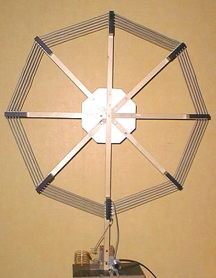
This is the first loop I build from a article in the QST from February 1996, it's 30 Inch-diameter, and it's designed by G2BZQ/WO for 80 M.

The first
one turn loop that I built was made from 75 Ohm TV Coax and with
a small explanation in the RSGB handbook
for radio amateurs. I used the outer screen from the coax and the
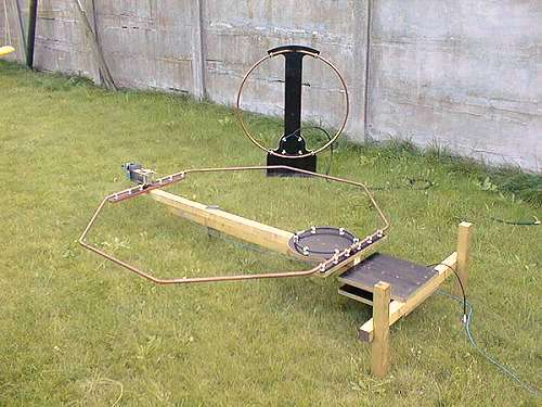
results of the loop where good.The next loop I built is a
octagon loop in 15mm copper tube with a circumference of
4.8 meter (16
feet).
The frequency
range of this loop goes from 14 MHz to 7 MHz and works fine.
The biggest
problem is the tuning capacitor, if you transmit with a power
of 100 W you
need a capacitor with a voltage rating of 5000 Volt.
A capacitor
which can handle this voltage is hard to find over here and if
you find one they are very expensive.
The first
capacitor I built was a design from GW3JPT from a article in the
RADIO
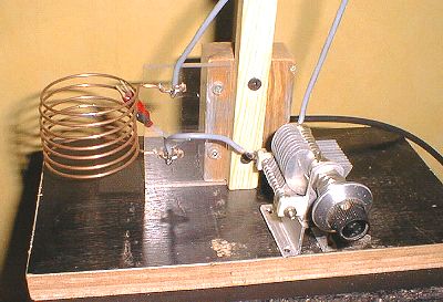
COMMUNICATION from February 1994. It is a split stator capacitor
with a capacitance of 140 pF and with a voltage rating of 6000
Volt.
The capacitor
is remote tuned with the use of a small BBQ spit motor.
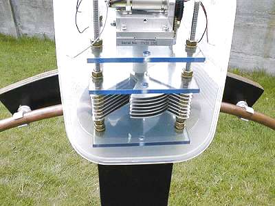
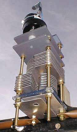
The second
capacitor I built is my own design and it's a butterfly capacitor
because the losses are lower than a split stator.
The
capacitance is 5-65 pF and the voltage rating is 7200 volts. I
used
it for the
small loop with a dia. of 800 mm (2.66 feet) and the frequency
range of this loop is from 28 MHz to 14 MHz. The Aluminum plates
of 1 mm
for the
capacitors are cut with a JIG SAW.
Most asked Questions:
I`d like
to talk a little more on your setup. it seems like something
whichI could get together if only some more data was available.
do you have anynotes etc still laying about since its build ?
The theory for calculating the loop is very simple.The
circumference of a magnetic loop is 1/4 wave of the
designfrequency.
Example for 14 MHz.
300 / 14 MHz = 21.428 m is 1
wave
21.428 / 4 = 5.357 m is 1/4 wave circumference
5.357 / 3.14 = 1.706 m diameter.
The
recommendations are that you can tune the loop from the design
frequency to the frequency divided by 2 to keep the effiecency
acceptable.
14 MHz / 2 = 7 MHz
I made the small loop (800mm / 31.5 ") from soft copper tube
on a role that you can buy in a plumbershop and it's easy to make
a nice circle if you draw on the ground a circle with a rope and
a piece of chalk.
For mounting the loop to the hardboard I used plastic clamps
that they use for mounting copper tube on the wall.
why is a
butterfly capacitor better?
For
high voltages and currents the use of Capacitors with wiper
contacs is not recomended. That's why they use capacitors in
serie's.The pro for serie's capacitors is that the voltage rating
is doubled.The anti is that the value of capacitance is divided
by 2.
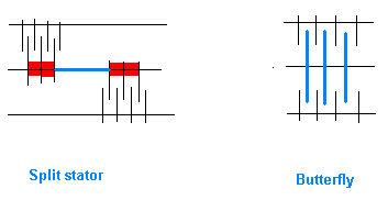
For the split
stator capacitor the 2 capacitors are connected in series
by the shaft (bleu) and the red spots on the first drawing are
losses.
For the butterfly capacitor the 2 capacitors are directly
connected
in series by the rotors and gives less losses.
Do you
know of anyone that has built a similar loop that
outperformed a garden variety dipole?
Compare antenna's is very difficult , sometimes I have for 60 %
better signals in RX and TX on the loops then on the dipole.
In Theorie is the performance of a magnetic loop - 0.4 dB lower
then a dipole or a vertical .
I have over here a homebrew trap dipole from 40-20-15-10m and the
height aboveground is only 7 m(23 ft), for a good performance on
40 m the dipolemust have a height of 1/2 wave above ground (
66ft). I don't have a radiation angle on 40 m and it's only good
for contacts in Europe and not good for DX, now the 1.5 m loop
tuned to 7 MHz with a effiecency of 38 % (38 w ERP ) and a angle
radiation of about 20 degrees performs
better than the dipole because the vertical magnetic loop only 1
M above
ground as a angle radiation and the dipole don't.
Another advantage is that the reception on a loop is mutch
better,
on 20m I have with the dipole S5 noise from the big city, if I
switch to the
loop I have S1 noise and hear stations who are buried in the
noise when
I use a dipole.
Coupling
loop dimensions?
I find that the best way to feed the loop is with the shielded
1/5 Faraday loop made from coax RG213 or RG8, I tried the gamma
match bud I had problems to keep the VSWR low on all Bands, the
shielded loop gives on all bands VSWR 1.1 and reduce more noise
pick-up then the gamma match.
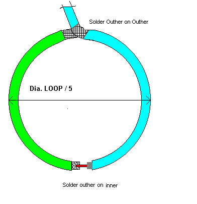
I found out that if you use a 1/5 Faraday loop, that the loop is
to big, making the loop smaller with 0.5 inch by the time in
circumference and checking with a field strength meter you can
see that the radiated power increase.
The place off
the feeding loop is placed at the electrically neutral point on
the loop and that is 180° from the capacitor and I have the best
results with the feeding loop close to the ground and the
capacitor far from the ground.
I was wondering if you worried about the resistance of the mechanical joints (copper pipe bolted to the capacitor) significantly reducing your radiation efficiency as I think the radiation of these antennas can get as low as .01 ohms
Soulder or
weld the capacitor plates is always the best, but I'm afraid if
you make the spacers and the plates in ALU that with welding
everything is gona bend from the heat and I know from practice (
I work in a maintenance workshop ) that welding ALU is coarse.
Another possibility is using all brass or copper and solder,
there are hams that using double PC board for the plates.
I made a QSO in phone with Florida, RPRT 5-5 and the other
station used a vertical antenna, with the small loop (800mm and
theoretical effiecency 41 % on 14 Mc) vertical in the garden and
the states side is through the house. I was very happy with the
results , so I think that a capacitor
maded with torqued compressed joints is good enough for using 100
W.
Have the
dissimilar metal joints weather well?
To keep the oxidation low on the dissimilar metals I used a thin
coat of vaseline after assemble the capacitor and with the tupper
ware a like plastic box it is good protect against all wheather
conditions.
How to find the radiation angle of the antenna?
Can it be found practically?
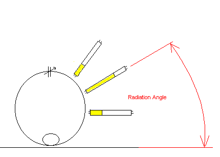
Finding the
radiaton of a magnetic loop is very easy, with a TL-lichgt tube
you can see it, with abt 10 w power on the the loop with the
TL-tube in the plain of the loop at right angle to the circle you
see the tube lightning, there where the the light is the farest
on the tube thats the radiation angle.
When you refer to washers, nuts and rods you use the term "M6".Please forgive my ignorance, but to what does "M6" refer? Does this mean 6mm?
M6 is
(M=metrical) and 6 is indeed 6 mm threaded rod and
you can compare the size with W1/4" (6.35mm) .
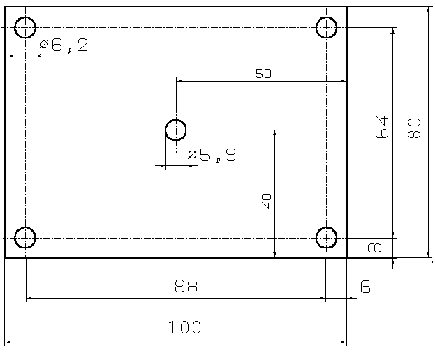
A very easy to build Piston Capacitor.
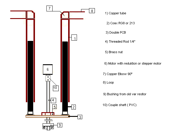
How to build your own Butterfly Capacitor.
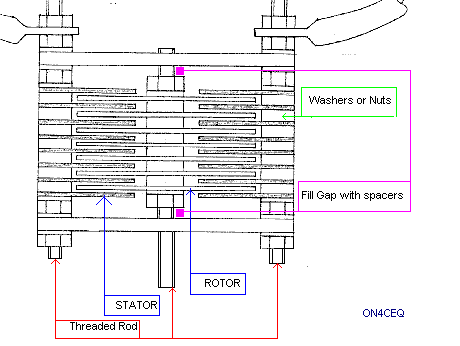
The best
material for the front and the back is CLEAR PVC 3 or 5 mm thick
as alternative you can use GREY PVC or 2 sheets pcboard together
with the copper removed .
The best material for the washers, nuts (M6) and threaded rod
(M6) is brass or stainless steel,( NON MAGNETIC MATERIALS for the
losses).
For the spacing of the vanes you can use 2 washers M6= ( 6Kv) or a nut M6 =( 12 Kv) if you use aluminum plate 1 mm thick.
If you use a
nut then the best thing to do is remove the thread by drilling
withO 6.2 mm.
The effective area for the vanes is 11.7 cm and with the
formula
for 2 washers = (0.0885 x 11.7 cm )/ 0.1 cm = 10.35 pF for 1 air gap.
for 1 nut =
(0.0885 x 11.7 cm )/0.2 cm = 5.17 pF for 1 air gap
Example:
If you you make a capacitor with 2 washers as spacing and you
make
5 rotor vanes and 6 stator vanes then you have 10 air gaps.
10.35 pF x 10 = 103 pF + 10 pF stray capacitance = 113 pF / 2 =
56 pF
The final result is a capacitor with a value from 5 - 56 pF.
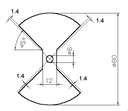
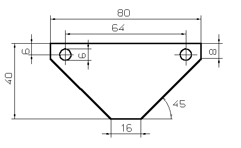
Last Update 03 December 1999. ON4CEQ Van Herck, Tony QTH: Anwerp( JO21FF ) BELGIUM.