|
|
|
Introduction
From time to time we have written about the small transmitting loop antenna, sometimes called the magnetic loop because its radiation is generated only from its magnetic field (and not any electric field). Much of the more recent design information is based on work carried out by Ted Hart W5QJR. This has been published in QST and in recent editions of the ARRL Antenna Handbook.
The articles I have seen concentrated on antennas for the HF bands and didn't appear to make any specific reference to the VHF spectrum. I thought it might be interesting to make a loop for the 2 metre band and see how it would perform. In the following paragraphs I describe how a 2 metre loop was assembled and adjusted and discuss the performance achieved.
The Loop
In describing the loop, I will refer to imperial measurements as well as metric. The reason for this is that the design formulae I have used, as given by Ted Hart, are in imperial form. The loop is circular with a diameter of 5.25 inches (133 mm) and made with 0.25 inch (6.4 mm) copper tube. The ring formed is open at the top to connect a variable tuning capacitor which is set to resonate with the inductance formed by the loop. To enable variable tuning of the loop, natural resonance formed by the loop inductance with its self capacitance must be at a frequency higher than the operating frequency. For the dimensions used, the loop resonates around 144-148 MHz with just 4 pF and, if the loop was a little larger, it would self resonate without added capacity at a frequency lower than 144MHz.
The larger the loop, the higher the radiation resistance and the higher the efficiency. Hence it is desirable to make it as large as possible. However, to allow tuning adjustment, the loop is about as large as it can go.
The copper loop can be considered as a one turn inductor which, when excited, has a magnetic field. As the field is not confined, energy from the circuit is lost in the form of radiation and shows up as a resistance called radiation resistance in series with the loop at its centre. At this point we might refer to figure 1 and see that the centre is the point designated C.
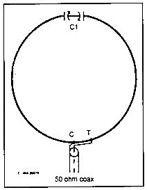
| Figure 1 - Magnetic loop for two metres. Loop diameter: 5.25 inches (133 mm). Material: Copper tube 0.25 inch (6.4 mm). Cl: Butterfly capacitor with range across stators of 2 to 5 pF. Matching tap: See text. |
Also in series with the radiation resistance is a loss resistance resulting from the RF resistance of the loop conductor and losses in the tuning capacitor. Radiation resistance is in the order of only a fraction of an ohm. To maintain high efficiency, the ratio of loss resistance to radiation resistance must be kept extremely low, hence the need for a conductor such as copper tube with low resistivity and a large surface area. In a larger loop made for the HF bands, I used 0.75 inch (19mm) copper tube but I thought that this was a bit cumbersome for the small 2 metre loop and settled for the 0.25 inch tube.
Another consideration is loss resistance in the wiper arms of the tuning capacitor. This is eliminated by connecting the loop across the two stator arms of a split stator capacitor so that the capacitance is the resultant value of the two halves in series. In this arrangement, the wiper arms float and are not in series with the tuned circuit. For this component, I used a small wide spaced nine plate butterfly capacitor which I measured to have a capacitance range of 2 to 5 pF across the stator plates and which nicely tuned around the 4 pF required. The wide spacing is also important as the loop operates at a very high Q and a high voltage is developed, even at quite low powers.
The constants for the loop have been calculated from formulae
given in the material by Ted Hart:
Loop Inductance 0.24 uH
Distributed Capacity 1.1 pF
Tuning Capacity 3.9 pF
Radiation
Resistance 0.35 ohm
Loss Resistance 0.06 ohm
Efficiency 85%
Loop Q
268
Potential across capacitor
For 25 watts - 1200 V RMS
For 100
watts - 2400 V RMS
If you are interested in the formulae used, they are published in the 15th edition of the ARRL Antenna Handbook (and possibly a later edition) and also reprinted with my article on these loops in Amateur Radio, November 1991.
Coupling
Assuming the loop is at resonance, a resistance can be seen between its centre C and a tap T part way up the loop. Its value is zero at the point C increasing as it is moved up and becoming a very high value where it joins the capacitor. A point T is found where it reflects 50 ohms and at this point we couple in our 50 ohm feed line. Of course this is a classical gamma match which normally includes a series capacitor to correct for the inductive reactance of the length of lead from the coax line to the tap point. For this application, I didn't think the capacitor was needed as a reactance correction would be reflected in resonating the whole thing as a unit. In practice I found that, provided the loop was properly resonated, the tap could be set to produce an SWR reading in the 50 ohm line of close to 1:1.
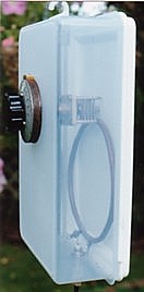
Assembly Detail
The general assembly of the loop and housing is shown in figures 2 and 3.
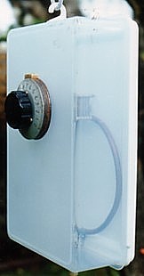
With such a high Q, tuning is very critical and some form of reduction drive, coupled to the variable capacitor, is essential to tune to resonance. I used a 6 to 1 vernier drive and, even with this reduction, adjustment is very critical and has to be finely set. With the capacitor used, the frequency range of 144 to 148 MHz is covered by seven degrees of shaft rotation.
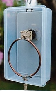
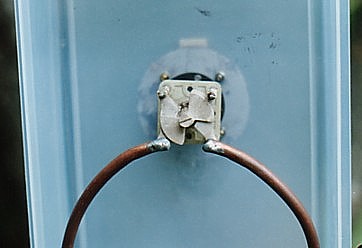
To connect the butterfly capacitor, the copper tube was drilled to take the stator legs. These were solidly soldered in place with the aim of minimising loss resistance. The butterfly capacitor and its connection to the copper tube is shown in figure 4.
 |  |
|
connection to the loop. |
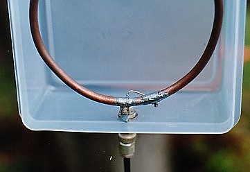
Two clamps made of copper strip were fitted for the matching connection. The one at the centre was soldered in place to ensure a low resistance connection. The other was made adjustable so that it could be moved along the copper tube to find the best position for low SWR. Once this was determined, the second clamp was also soldered in place. The 50 ohm feedline is connected via a BNC panel mounted connector. The outer part of the connector joins the centre clamp via a soldered lug. A stub wire is connected from the centre lug of the connector to tap T. Following tap adjustment, this ended up around 23 mm long and spaced out from the copper tube about 15 mm. A closer view of the coupling system is shown in figure 5.
I needed some sort of non metallic housing to mount the vernier dial and the coax connector and did a search of the local Big W and Target stores for a suitable box. I selected a nice polythene "lunch box" which measured 155 mm x 255 mm x 75 mm. As you can see from the photographs, the 255 mm dimension is quite a bit more than I needed but the other two dimensions suited me fine.
I liked the idea of the lunch box name for my antenna but the one selected is really more than that as it is suitable for microwave oven use. This is good because, if the material has low dielectric absorption at microwave frequencies, it will also have low absorption around the VHF antenna. The box idea is also useful for outside use as it can be sealed easily against the elements with a silicone sealer.
Components
Perhaps it is of interest to discuss the source of all the components used. The copper tube was left over from a household plumbing job. The butterfly capacitor was found in the spare capacitor box. A few of these often change hands at amateur radio trading marts and sometimes they fall into my hands. I think most of them were retrieved from early mobile TCA VHF transceivers such as the 1675 and 1677.
The nylon hook at the top of the box was found in my box of sailing boat spares. The vernier dial was given to me some 50 years ago by a gentleman who had taken it from a wartime Japanese transceiver he had dismantled. The BNC connector was one of a number retrieved some time ago from some discarded commercial gear. The box I have already told you about and this cost just under five dollars. To me, recycling whatever I can at minimal cost is much of what amateur radio is all about.
Performance
The loop is mounted so that its plane is vertical and the antenna radiates a vertically polarised signal. The signal is bi-directional with lobes peaking in line with the plane of the loop. The lobes are fairly broad and the loop only needs to be oriented in the general direction required. However, fairly sharp nodes occur at right angles to the plane of the loop.
As indicated before, the tuning is very sharp and it can be put off tune by hand capacitance. To manually tune, one must be in visual distance of an SWR meter in the transmission line and the capacitance tuning dial is operated at arm's length to minimise body capacitance effects. Off tune, the SWR indicated is high. To resonate, carefully tune for a sharp dip in reflected power.
With the loop tuned properly to resonance and facing in the right direction, the results achieved seemed comparable with a J-Pole antenna used at the same height. On receiving, the two antennas gave comparable S meter readings. However, the problem with these loops is their narrow bandwidth. To maintain an SWR reading within 1.5:1, this one is limited to a band of little more than 100 kHz. To go beyond that, the butterfly capacitor must be retuned. There is no problem maintaining an SWR close to 1:1 over the whole 144 to 148 MHz but the capacitor must be reset for the particular limited section of the band used.
I had no problem working local repeaters with this antenna and I had adequate received signal fed to the transceiver. However, if the loop is tuned up nicely on the transmit frequency to trigger the repeater, it is way off tune on the receive frequency 600 kHz away and hence the receive signal is attenuated. This could be a problem where the signal from the repeater is of marginal strength.
Conclusions
The two metre magnetic loop is a compact antenna which can easily be hung up under the eaves, the carport, or any other place where space is limited including indoors. It is probably best suited to a situation where a dedicated transceiver operates on a fixed frequency such as a single packet channel. Properly tuned up for the single frequency and directed towards the other station, it appears to work as well as a full size vertical dipole.
However, in its static form, it has a narrow bandwidth and has to be tuned to track across the band. This makes it less suitable to cover a general range of channels across the band and, to achieve this, remote motor tuning would need to be considered. It would seem to me that if this extra complication was the option, it might be far simpler to find space to fit in a J-Pole or other wider bandwidth antenna.
References
1 The ARRL Antenna Handbook, 15th Edition, Chapter 5, Loop Antennas.
2 Lloyd Butler VK5BR - Some Experiments with the Small Transmitting Loop Aerial - Amateur Radio, November 1991.