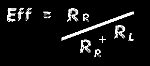
Some of the formulae behind magnetic loop design are included below. I am grateful to Reg G4FGQ for these. I have used Ln to refer to natural logs because I'm a Sinclair/BBC baby I suppose...

For a square loop the inductance is smaller for the same perimeter and the value 2.451 changes to 2.853 - the area within the loop being the main variable.
Above a few hundred kHz RF flows in the surface or skin of a conductor - the material for the loop can be hollow tube, or perhaps the outer braid of good quality co-axial feeder.

and the tuning capacitor setting in pico-farads is calculated:

.
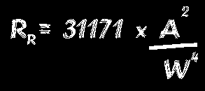
31171 ( PI to the fourth power x 320 ) multiplied by the Area squared (A*A), divided by the Wavelength to the fourth power (W**4)


The above formulae apply only to small loops with perimeters not greater than 1/5 of a wavelength. They do not apply accurately to loops near to the ground, at a height less than about half a loop diameter, because heavy loop currents induce currents in the ground in a manner similar to electric induction-heating furnaces. This power loss is represented by an additional loss resistance inside the loop. Reg. G4FGQ
Email GW0TQM

Carl GW0TQM's Magnetic loop page
Contributions comments and STL links welcomed.
Magloop home What? Using Building BASIC Software Links More reading and reports
Sign
the Magloop Guestbook ![]() View
the magloop Guestbook
View
the magloop Guestbook