Morse Code Decoder Circuit - Using a PIC Microcontroller
IK3OIL
9/30/2006 - This project is right up my alley! I gathered all parts and started building the circuit on a breadboard first before designing the circuit board to etch. - KC2NDA
12/02/2007 - I have been getting a lot of emails about this project. Most of them are because of the bad source code listing at the end of the author's notes. I have seen this problem all over the web and I too have ran into the same problem when compiling the code. I am assuming that the code has been copied and pasted so many times that things have been jumbled. You will notice that the code does not compile because of the duplicate labels "dlp1". I have not had time to fully break apart the code yet, but I am assuming the extra code that exists with the duplicate label is extraneous and should be removed. Once this block of code is removed, it should compile. I modified the code and reposted it. I also included the compiled hex file as well. NOTE: I changed the header to be used with the PIC16F84A since those are readily available from Microchip.
Click Here for the revised PIC assembly source code.
Click Here for the revised HEX assembly source code.
Original Author/Designer Notes
by Lawrence Foltzer, KE6UDL
So you want to become a HAM, or you've got one of those no-code licences, but like me feel somewhat lacking,... not having obtaining that age old badge of proficiency that differientiated the HAM from other radio operators. However, like thousands and thousands of others, you have trouble learning the code. The problem for most people is the non-real time nature of the process, i.e., writing down the last character while listening to, and decoding the signature of the next character. Furthermore, when you make a mistake, the entire process collapses as your mind tries to perform error correction, trying to fill in the missing blanks, causing you to miss even more characters.
One way out of this delimma is to remove the burden of writing down the characters altogether during the process of building up your code speed. But to do this you need a device that copies and displays the code in parallel with you, which is what the stand-alone device described in this article is designed to perform.
The decoder is designed for code speeds ranging from about 6 words per minute (WPM) to greater than 36 WPM. The rate adaptive algorithm responds quickly to code speed changes, so you can copy both halves of a QSO, even when the parties transmit at different rates.
The Hardware
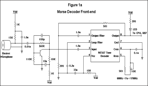
The schematic of the decoder is shown in figures 1a and 1b. It consists of four major pieces, all powered from a set of four (4) AA cells. The first piece, the front-end, is composed of an electret microphone and a common emitter transistor amplifier. This building block provides a wireless hookup to your radio receiver or code practice oscillator. The 15Kohm resistor biasing the electret may have to be changed to a different value, depending on the requirements of the electret you use. In addition to providing gain, the transistor amplifier also acts as a first level bandpass filter. Its band edges are determined by the size of the coupling capacitors, and the feedback capacitor between Q1's base and collector terminals.
The second functional block is a narrowband PLL based tone detector, consisting of a tunable NE567 PLL tone decoder (Click here for the datasheet). There's nothing radical here, the circuit is right out of the manufacturers data sheet, and employs hysteresis for chatter prevention to, in effect, debounce the decoded signal. The small signal, narrowband detection capability of this block enables one to easily discriminate one signal from another, even when the signal you are copying is substantially smaller that the adjacent channel interference, as long as there is 100Hz or so frequency separation between them. The output of the detector is a one-zero pattern replicating the DIT-DAH sequence of the received signal. This output drives both an input to the PIC16F84 microcontroller and an LED which is used as a receiver tuning aid. More on that later.
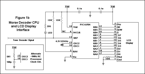
The third functional block is the PIC16F84 (Click here for the datasheet) microcontroller (CPU). Its function is to measure the duration of the one-zero input string from the tone decoder, and translate the pattern into DITs, DAHs, symbol spaces, character spaces, or word spaces. The CPU also perfoms input signal debounce, just in case the front-end missed something. This feature was one I found absolutely essential for the robust operation of the decoder under varying signal conditions.
The CPU also has the task of code speed adaptation, which it performs by performing a running average on the various components of the signal in real time. The symbol averages are then used to compute time threshold levels for correct symbol interpretation. As each of the symbols are received, a "code word" is assembled and used to lookup/convert to its ASCII equivalent character for display. The CPU also drives an LED in synchronism with the input. While this feature was used initially as a debug aid, it also serves as a tuning aid, and verifies that the CPU is receiving what the front-end sent. Finally, the CPU interfaces to the LCD line display, sending ASCII characters to it and monitoring LCD status.
The final building block is the LCD display. I used a surplus display that uses an Hitachi HD44780 LCD controller based interface. You can purchase a similiar OPTREX unit through DigiKey Electronics, P/N DCM-117A, for about $12.00, or Hitachi display I used from me for $8.00, while my limited supply lasts.
In the prototype implementation of the CPU, figure 1a, I used a crystal to generate the CPU clock since I had a sizeable stash of crystals in my junk box. But one could just as easily use the RC oscillator configuration since the PIC16F84 spends most of its time sitting around anyway, and could easily do the job running at 1MHz.
Construction
I built my decoder as two separate pieces, and recommend this approach for two reasons.
1) It allows you to distance the CPU and LCD away from your receiver, minimizing digital noise coupling the the receiver.
2) It keeps the CPU and LCD clock noise away from the sensitive front-end of the electret amplifier and PLL.
The front end was constructed using point-to-point wiring on a 2.0" by 2.5" piece of perf-board. I wrapped the edges with adhesive backed copper tape to provide a convenient place to ground components. The 10Kohm variable resistor off pin 5 of the NE567 provides frequency adjustment capability so you can tune it to the frequency of a code practice oscillator, or to a comfortable pitch to copy signals off the airwaves. A three (3) wire interface connects the front-end to the CPU/LCD assembly, carrying the signal, power and ground.
The CPU was also point-to-point wired on a 2" by 2.5" perf-board. I decided to interconnect the CPU and LCD using a 14 pin (2 * 7) plug and socket arrangement I made up for easy connect and disconnect. I used machined pin and collet type sockets and pins for this connection. A three pin header socket was used to make the connection to the front-end consisting of power, ground, and the decoder output.
The PIC16F84 Assembler/Machine Code
The firmware for this project is shown in Listing 1. This code was written in Microchip's native assemby language, and only took 365 instruction to implement. To help follow the flow, read the pseudocode at the end of the listing. You will find other important design details at the end of the listing also. The heart of the code is two running average buffers that keep tabs on the length of the four previous DIT and DAH interval samples. With these short buffers, speed adaptation appears almost instantanous. But I must confess that I didn't start out with this approach. In my first implemetation, I averaged DITs and DAHs in the same buffer, since over time there would roughly be an equal number of DITs and DAHs, and the average, therefore, would be (2 DITs long) right in the middle and be the perfect symbol discriminator. But when you copy sequences like "he is 55 .....", the symbol decision threshold becomes corrupted quickly unless the buffer depth is quite large. But a larger buffer means a slow code speed adaptation rate, so I quickly abandoned that approach in favor of the dual buffer approach.
The three subroutines at the end of the code drive the LCD display interface. Perhaps you will find uses for them in other PIC related projects.
DIT DAH DIT DIT DAH DAH DAH DAH DAH DAH DAH DIT DAH DAH !
DAH DIT DAH DIT DAH DIT DIT DIT DIT DIT DIT DAH DAH DIT DIT DIT DAH DIT DIT
DAH DIT DAH
Click Here for the PIC assembly source code.
Перевод
Этот проект является правильным мой переулок! Я собрал все части и начали строить схемы на макете, прежде чем проектировании печатной платы для травления. - KC2NDA
12/02/2007 - Я получил много писем об этом проекте. Большинство из них из-за плохой листинга исходного кода в конце заметок автора. Я видел это проблема всей сети, и я тоже столкнулся с той же проблемой при компиляции кода. Я предполагаю, что код был скопирован и вставлен столько раз, что вещи были перемешаны. Вы увидите, что код не компилируется из-за дубликат метки "dlp1". У меня не было времени, чтобы полностью развалится кода нет, но я предполагаю, дополнительный код, который существует с дубликат метки посторонних и должны быть удалены. После этого блок кода, удалено, оно должно собрать. Я изменил код и повторно отправил его. Я также включил составлен шестнадцатеричный файл, а также. Примечание: Я изменил заголовок, который будет использоваться с PIC16F84A поскольку они являются доступными из Microchip. Нажмите здесь для пересмотренный код ассемблера ПОС. Нажмите здесь для пересмотренный код ассемблера HEX.
Автор Оригинала / Notes Designer
Лоуренс Foltzer, KE6UDL
Итак, вы хотите стать HAM, или у вас есть один из тех не-код лицензии, но, как я чувствую себя немного не хватает, ... не имеющие получение этого возраста старый знак, что знание differientiated HAM от других операторов радио. Однако, как тысячи и тысячи других, у вас есть проблемы изучения кода. Проблема для большинства людей, не в режиме реального времени характер процесса, то есть, записывая последний символ, слушая, и декодирования подписи следующего символа. Кроме того, если вы допустили ошибку, весь процесс рушится, как ваш разум пытается выполнить коррекцию ошибок, пытаясь заполнить недостающие пробелы, в результате чего вы пропустите еще более символов.
Один выход из этой delimma заключается в удалении бремя записывать символы в целом в процессе создания кода скорости. Но для этого вам нужно устройство, которое копирует и отображает код параллельно с вами, что и автономные устройства, описанного в этой статье, предназначен для выполнения.
Декодер предназначен для кода скорости в пределах от 6 слов в минуту (WPM), чтобы больше 36 слов в минуту. Скорость адаптивный алгоритм быстро реагирует на изменения кода скорости, так что вы можете копировать обе половинки QSO, даже тогда, когда стороны передают с различной скоростью.
Схема декодера показано на рисунках 1a и 1b. Она состоит из четырех основных частей, все питается от набора из четырех (4) А. А. клеток. Первая часть, передний конец, состоит из электретный микрофон и усилителя с общим эмиттером транзистора. Этот блок обеспечивает беспроводное подключение к приемнику радио или генератор кода практике. 15Kohm резисторов смещения электретного может быть изменено на другое значение, в зависимости от требований электретный вы используете. В дополнение к обеспечению усиления транзисторного усилителя также выступает в качестве первого полосового фильтра уровня. Ее края полосы определяется размер конденсаторов, и конденсатор обратной связи между базой Q1 и коллекционер терминалов.
Второй функциональный блок PLL узкополосный детектор на основе тона, состоящая из настраиваемых NE567 декодер тон PLL (Щелкните здесь для просмотра таблицы). Там нет ничего радикального здесь, схема прямо из листа производителей данных и использует гистерезиса для болтовни профилактики, по сути, Debounce декодированный сигнал. Малого сигнала, узкополосного возможность обнаружения этого блока позволяет легко различать один сигнал от другого, даже когда сигнал копировании существенно меньше, что вмешательство соседних каналов, пока есть 100 Гц или около того частотного разделения между ними. На выходе детектора является одним нуля модель репликации ДИТ-DAH последовательность принимаемого сигнала. Этот выход управляет как вклад в PIC16F84 микроконтроллера и светодиод, который используется в качестве помощи настройки приемника. Подробнее об этом позже.
Третий функциональный блок PIC16F84 (Щелкните здесь для просмотра таблицы) микроконтроллера (CPU). Его функция заключается в измерении продолжительности одного нуля входной строки из тон декодер, и перевести рисунок в Диц, DAHs, символ пространства, характер пространства, или слово пространства. Процессор также perfoms дребезга входного сигнала, только в том случае, интерфейсные что-то пропустил. Эта функция была одна я нашел абсолютно необходимо для надежной работы декодера при различных условиях сигнал.
Процессор также имеет своей задачей код скорость адаптации, которые он выполняет, выполняя скользящее среднее на различных компонентов сигнала в режиме реального времени. Символ средние затем используется для вычисления уровня порогового времени для правильной интерпретации символа. В каждом из символов полученной "кодовое слово" собирается и используется для поиска / преобразовать его эквивалент ASCII символов на дисплее. Процессор также управляет светодиодной синхронно с входом. Хотя эта особенность была использована сначала в качестве отладки помощь, он также служит в качестве тюнинга помощи, и проверяет, что процессор получает то, что внешний отправлены. Наконец, процессор интерфейсов к строке дисплея LCD, отправка ASCII символов к нему и контроль ЖК-дисплеем.
Последний блок является ЖК-дисплей. Я использовал излишки дисплей, который использует Hitachi HD44780 LCD контроллер интерфейса. Вы можете приобрести похожий блок Optrex через Конденсаторы Electronics, P / N DCM-117A, по цене около $ 12,00, или Hitachi отображения я у меня на $ 8.00, в то время как мой ограниченный запас длится.
В прототипе реализации процессора, рисунке 1а, я использовал кристалл для генерации тактовой частоты процессора, так как у меня был значительный запас кристаллов в мой хлам окно. Но можно так же легко использовать RC генератор конфигурации с PIC16F84 проводит большую часть своего времени сидеть в любом случае, и легко может сделать работу работающих на 1 МГц.
Строительство
Я построил свой декодер в виде двух отдельных частей, а также рекомендовать такой подход по двум причинам.
1) Она позволяет дистанцироваться процессора и ЖК от приемника, сводя к минимуму шум цифровой связи приемника.
2) Он держит процессор и ЖК-часы шумов от чувствительных переднего конца усилителя электретных и PLL.
Передняя часть была построена с использованием точка-точка подключения на 2.0 "2.5" кусок перфорация борту. Я завернул края с клейкой основой медной ленты обеспечить удобное место, чтобы земля компонентов. 10 кОм переменный резистор с контактным 5 NE567 предоставляет возможность подстройки частоты, таким образом Вы можете настроить его на частоту генератора практике код, или в удобное поле для копирования сигналов от эфира. Три (3) проводной интерфейс соединяет интерфейс к CPU / ЖК-монтаж, проведение сигнала, питания и заземления.
Процессор также точка-точка проводного на 2 "на 2,5" перфорация борту. Я решил для соединения процессора и ЖК использованием 14-контактный (2 * 7), разъем договоренности, я составил для легкого подключения и отключения. Я использовал обработанные контактный и цангового типа разъемов и выводов для данного соединения. Трех контактный разъем розетка была использована для подключения к внешнему, состоящая из питания, земли и выходе декодера.
Прошивки для этого проекта показан в листинге 1. Этот код был написан на родном языке assemby Microchip, и только взял 365 инструкция для выполнения. Чтобы следить за потоком, читать псевдокод в конце списка. Вы найдете другие важные детали дизайна в конце списка также. Сердце код состоит из двух скользящее среднее буферов, которые следят за длиной четыре предыдущих DIT и DAH образцы интервала. В этих коротких буферов, скорость адаптации кажется почти instantanous. Но я должен признаться, что я не начинаю с таким подходом. В своем первом реализация, я насчитал Диц и DAHs в том же буфере, так как с течением времени было бы быть примерно равное количество Диц и DAHs, а средняя, ??следовательно, будет (2 Диц долго) прямо в центре и быть совершенный дискриминатор символ. Но при копировании последовательности, как "он составляет 55 .....", порог символ решение поврежден быстро, если буфер глубины, достаточно велика. Но больший буфер означает медленный код скорость адаптации скорости, так что я быстро отказалась от такого подхода в пользу двойной подход буфера.
Три подпрограммы в конце кода управлять интерфейс ЖК-дисплей. Возможно, вы найдете для использования их в других проектах, связанных с ПИК.