Last revision: 2003/06/16
The main features are:
- Small size - 3' (1m.) diameter
- Light weight - 1 lb. 2 oz. (511 g.)
- No counterpoise needed
- About a 1.5 octave tuning range
- Easy tune-up
- High-Q circuit providing a great pre-selector for the receiver front-end
- Good near-field electric field noise immunity (fed with a Faraday-shielded feed loop)
- Quick and easy set-up / tear-down
- Some directivity on the lowest two bands (approaching less than 1/10 wavelength in diameter)
Disassembled for storage or backpacking..
 Ready for QSOs (about 1.5 minutes field assembly time) |
Main Loop
The main loop is made from shield braid from 9' (3m) of RG-8 or RG-11 coax. Remove the outer insulation (be careful to not nick or cut the shield) and the inner insulation and conductor. Bunch up the shield and insert 9' of 3/8" bulb polyfoam caulk-backing into the braid to replace the inner insulation / conductor. After that, spray the entire braid assembly with Krylon® clear-coat to prevent copper oxide build-up. Place nine 2" long pieces of heat-shrink tubing on the main loop spaced to match the struts (to act as strain-reliefs for the corners) and where the ends enter the main tuner box grommets. The main loop ends are then soldered to the main tuning capacitor stators, there is no connection to the rotor.The main loop is formed into a octagon with eight 1.5' long 1/8" diameter fiberglass spreader rods radiating from a center hub formed of brass ferrules (SteelWorks® brass round tube, 5/32" O.D.) soldered onto a small double-sided PC board octagon (1 3/8" face-to-face). The ends of seven of the rods have 7/16" spacing plastic cable nail-downs (with the rod going into the hole where the original nail was) facing outward to hold the loop. There is a slight amount of tension created by the length of the loop (if not, shorten the loop before final tune-up via the fixed capacitor trim) versus the radius, plus the 'springyness' of the loop which firms up the loop assembly and keeps it in place. The main tuner box has a single ferrule mounted on the back to take the eighth rod.
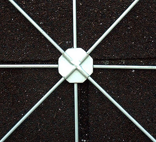
Spreader Hub
Feed Loop
The feed for the antenna is easy, it is made with RG-58/U coax. Don't use the foam version of this coax as it will deform too easily at the junction point. The open shield at the top-center of the loop creates a Faraday shielded loop that inductively couples into the resonant circuit of the main loop. For those of you who are thinking of resizing the antenna - this loop should be 1/5 the diameter of the main loop. You can use a clamp-on ferrite bead just below the feedloop to help isolate the feedline coax. The feedloop is then simply tie-wrapped to the bottom support rod - two at the top in a crossing pattern and one at the bottom. The following diagram shows how to make it..
Feed loop construction
Capacitor Requirements
These antennas have several building and component requirements that have plagued their widespread usage in the past. One of these issues is the very high voltage developed across the tuning capacitor (can exceed 1KV even at QRP levels). This requires a high voltage / high-Q component with a balanced structure (for current distribution). Another issue is the very sharp tuning created by the high-Q circuit. This can be changed from a problem to an asset (great pre-selector) with the right design..A butterfly capacitor fills the requirements, but creates new ones.. To cover multiple ham bands either a large capacitor with a vernier drive is needed (very expensive these days and too heavy for backpacking) or a small 'fine-tuning' capacitor with a high voltage / high-Q fixed capacitor for each band. Even small butterfly capacitors are around $47 - $85 each and high voltage / high-Q fixed capacitors are practically nonexistent. I choose the latter method and solved the cost and availability problems by making my own parts! Keep in mind that even with the improved parts that this still a QRP antenna. More than 5 watts applied will destroy the capacitors and / or de-tune the antenna by a capacitance shift from over-heating. There is a safety margin designed into the antenna, but you really can't go QRO!
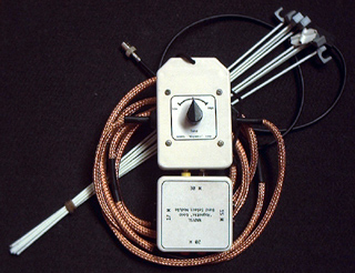
Tuning Capacitor
The butterfly capacitor (4-12pF, delta C = 8pF) is made using printed circuit techniques, but you can replace it with a 10 pF (measured stator-to-stator, fully meshed rotor) butterfly with a 1KV (or better) dielectric breakdown. My capacitor has some nice features not found with the 'standard' parts - high dielectric breakdown (uses air dielectric with a large gap - hard to find / expensive in small capacitance values), lower cost, built-in stops for the 90 degrees of rotation and designed-in connections for both the loop and band-select fixed capacitor (minimizes stray capacitance). If you would like to purchase this component for your project please see the bottom of this page..|
Printed circuit butterfly capacitor |
Fixed Capacitors (Band Selector)
The fixed capacitors are created using a microwave substrate (Teflon/ceramic/glass material) that has a dielectric constant of 6 (for size reasons) and a substrate thickness of 0.05". Do not attempt to use fiberglass printed circuit board, it will break down even at QRP levels! Believe me, I tried it when looking to lower the cost of the antenna.. If you have difficulty obtaining the microwave substrate, you can also purchase a set of 4 capacitor pieces (pre-trimmed size) from me at the bottom of this page. Band selection is done by plugging in the desired capacitor via banana jacks along the outside edge of the selector box.These capacitors are trimmed to the exact values by starting with an area larger than required and then cutting off small amounts of the substrate until the antenna tunes up. Do not try using a capacitance meter to trim the capacitors, do it on the antenna so that the stray capacitance of your build is accounted for. The corners should be trimmed first to reduce the chances of arcing.
Start by setting the main tuning to the high end (minimum capacitance) and trim small bits off of the fixed capacitor until the receiver noise increases at the middle of the band. Then transmit a carrier (still at the middle of the band) and check the SWR. Continue to trim the capacitor for lowest SWR (DO NOT trim while transmitting!). When that is achieved, start moving the tuning capacitor down to the middle of it's range (in small steps), trimming the fixed capacitor as you go. Stop when lowest SWR is at the middle of the tuning range. Repeat for each band..
|
Capacitance needed by band (fixed capacitor + tuner capacitor + stray capacitance) (your results will vary with stray capacitance differences from your building technique) |
||
|---|---|---|
| Band | Total Capacitance |
Fixed Capacitor Length X Width = Final pF (includes extra area for trimming corners and tune) |
| 30M | 90 pF | 2.5" X 1.5" = 82pF |
| 20M | 47 pF | 1.25" X 1.5" = 39 pF |
| 17M | 28.5 pF | 1" X 1" = 20.5pF |
| 15M | 21 pF | 0.75" X 1" = 13pF |
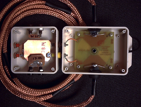
Fixed capacitors and main tuner
Other Bands..
With this size of loop you can get the antenna to tune other bands. However, it will become more of a compromise antenna, either the bandwidth will become very narrow and efficiency will drop (40M) or tuning will become very touchy and tight (12-10M). I have modified my 15M fixed capacitor to include the 12M band by trimming more off of it so that 15M tunes at the bottom of the main tuning capacitor's range and 12M tunes at the top. By removing the band select box and only using the main tuning capacitor 10M can be used with practice. It is very sensitive to body capacitance and requires a steady hand.. But I do have a six band antenna now. Below is a chart of fixed capacitor setups for the other bands.|
Capacitance needed by band (fixed capacitor + tuner capacitor + stray capacitance) (your results will vary with stray capacitance differences from your building technique) |
||
|---|---|---|
| Band | Total Capacitance |
Fixed Capacitor Length X Width = Final pF (includes extra area for trimming corners and tune) |
| 40M | 182 pF |
4.5" X 1.5" = 170pF (efficiency is low and bandwidth is ~ 9.5 kHz) |
| 12M | 14.7 pF | 0.3" X 1" = 6.7 pF |
| 10M | 11 pF | none - main tuning capacitor only |
Bandwidth
This antenna is not for people that want to QSY from one end of a band to the other without retuning simply because it is a high-Q circuit. You can QSY up or down 5 kilohertz (worst case) to 22 kilohertz (best case) without retuning. This high-Q is an advantage for receivers without great selectivity (direct conversion QRP rigs) as it does help reduce overload from strong off-frequency QRM.| Bandwidth for < 2/1 SWR (without re-tuning, assumes 1/1 SWR at resonance) | |
|---|---|
| Band | Bandwidth |
| 30M | 12 kHz |
| 20M | 20 kHz |
| 17M | 35 kHz |
| 15M | 50 kHz |
If you are changing frequency often, I recommend that you keep the antenna near your rig (typical of portable and apartment operation). I have used this antenna only five feet away from my operating position and a couple of feet off of the ground and still worked 4000 mile / 5 watt SSB DX! The radiation dosage has been calculated to be safe using QRP power levels, just don't sit 6 inches away from it on the edge plane (greatest radiation is not broadside like a dipole)..
Simple plot of radiation pattern
Tuning and Operation
To tune the antenna simply select the band desired by plugging in that side of the selector box, peak the receiver noise (best with receiver AVC off) with the tuning knob to get close to a low SWR, transmit a carrier and tune for lowest SWR. Then slightly tune to the low side of that resonance (to counteract body capacitance), remove your hand from the knob and the SWR will drop right back to minimum with a little practice. The amount of compensation varies by band, with the lower frequencies being affected less. I have not seen a SWR greater than 1.5 to 1 on any band when tuned properly (15M is the 'touchiest' due to the small amount of capacitance needed for resonance). Most of the time a 1 to 1 SWR is easily achieved.|
Click here for a Operation Training Video (QuickTime - MPEG4 encoded, 5 minutes long) Dial-up users, this is a 5.1Mb file, you will have a bit of a wait.. If only the audio plays you need to update your QuickTime. |
Do keep the antenna away from large pieces of metal (or above them - say a balcony rail) for best operation and ease of tuning. DO NOT touch the braid of the main loop when transmitting - remember that there is a very high potential (especially near the tuning capacitor) on the main loop! Touching the antenna would theoretically kill the Q of the circuit, detune the antenna and the potential would drop. I have had a RF burn in the past (not from this antenna) and do not want to test the theory! Please don't try it..
Can this antenna be used for shortwave listening?
Yes indeed! Simply replace the band-select box with a 20-490 pF vernier-drive variable capacitor and you have a great little SWL antenna that tunes from 4.5 to 20 Mhz. Do NOT attempt to transmit with this kind of capacitor, the gap between the plates is too small and it will break down (arc) even at QRP levels. Most variable capacitors in this range have a wiper riding on the rotor to connect it to the frame for low noise during tuning, mine (from the 'junk' box) did not. So I soldered about 1.5" of de-soldering braid from the brass shaft to the steel frame in a loop that allowed for the 180° of rotation and I was rewarded with nice and quiet tuning.. The capacitor I use has about a 5 to 1 ratio on the built-in vernier drive and it tunes smoothly. You will find that the butterfly capacitor is still handy for fine tuning at the top and bottom of the SW capacitor's range. At the top you cover a lot of MHz with little rotation and at the bottom the narrow bandwidth requires retuning for a small frequency shift.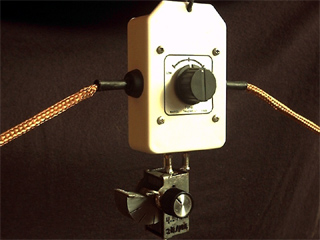
My SWL capacitor 'mod'
Not into building?
I am prepared for low volume production of this antenna for those folks that are not inclined to build, test and calibrate it. I reserve the right to make design changes in the pursuit of product improvement.. See the shopping cart below if you are interested.. If you have any questions just me!72 / 73,
Doug Wilson