Introduction
The February, 2000 issue of Amateur Radio (ref. 1) contained an article I had submitted on an LF transmitter. The transmitter was designed for CW operation but the power amplifier was operated in a linear mode and it was only a matter of replacing the VFO with some form of AM or sideband generator with an LF output to operate on speech.
The article was followed up with a further article (Amateur Radio September 2000, ref 2) on a Single Sideband Generator using the phasing technique. The design aimed at making a stand-alone unit because of the possibility of using the unit at a site away from the amateur station. However it was pointed out that a simpler arrangement might be achieved at the amateur station site by heterodyning down from the HF output of the local HF transceiver. This third article describes a circuit designed to do that conversion and provide sufficient LF output level to drive the original power amplifier.
The Converter circuit
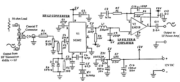
The circuit diagram of the converter is shown in figure 1. The conversion takes place in V1 (type NE602). The V1 circuit is almost identical to that used in my Active Loop Converter (Amateur Radio July, 2000 - ref 3) except that the input and output frequencies are reversed. I used the same 4 MHz xtal as in the receive converter as I had another one spare. Most HF amateur transceivers tune up to 4 MHz on the 3.5 MHz band so that it is simply a matter of setting the transceiver frequency to 4 MHz minus the LF transmission frequency. (4 MHz plus LF transmission frequency could also be used if the transceiver is tuneable above the 4 MHz. - This would make easier setting of the required HF frequency. Of course there is nothing to prevent some other crystal frequency being used with appropriate setting of the transceiver output frequency. ).
The overall circuit gain of V1 and V2 is arranged so that the HF input to V1 operates around 20 to 30 mVPP for peak signal level. This was chosen as it was anticipated that above these levels, steep increase in the level of intermodulation products could cause distortion in the audio signal when demodulated. This effect, relevant to the NE602, was discussed in one of my previous articles ( A.R. Jan 1994, ref 4).
HF Transmitter Pick-up
There is no point in running the HF transmitter at high output level to generate a signal. I reduced the power on an FT101B used to around 1 watt by backing off drive to the PA. The output is loaded into a dummy load and paralleled off to an attenuation network R1-RV1-R2-R3. (Note the connection via the coaxial T connector in figure 1.). The precise amount of drive for a given HF transmitter power is set by RV1. Diodes D1 and D2 provide some protection to V1 in the event of excessive RF level.
LF Output
To attenuate mixing products above 200 kHz, the LF output from converter V1 is fed into a low pass network formed by L1-C9 and the feedback circuit of V2. The following LF Power Amplifier requires 6VPP at maximum swing and stage V2 raises the output from V1 to this level. The circuit is similar to that used at the output of SSB modulator (ref 2) but the gain has been raised from the original value of 10 to around 70 by changing the values of R5 and C8 to those shown. With this arrangement, the 6VPP is achieved with around 25mV of HF signal at V1 input. Maximum possible output level from V2 is 9VPP.
DC Power
The complete converter is powered from 12V DC and when operated in conjunction with the Power Amplifier (ref 1), the supply it is picked up from 12V in the Amplifier unit. A further 6V rail is derived with Zener diode ZR1 and resistor R7. This is used to power the NE602 converter, V1 and to set the operating point of amplifier V2 at half its12V operating supply. Load current at 12 volts is 15mA.
Components
There are no specialised components. L1 is a miniature choke available from electronics stores. The two I/Cs are mounted in 8 pin DIL sockets. The 4MHz crystal was a HC25 style but any crystal of suitable frequency could have been used. The precise frequency of the crystal can be adjusted by varying the values of C4 and C5. The input connectors, including the T, are BNC type but some other type could have been used. The small components (except R1) are mounted and interconnected on a piece of blank circuit board. To prevent stray coupling from the high level at the input to R1 from getting into the rest of the circuit, I found it necessary to remove R1 from the board and shield it and its connecting lead to the input connector. The complete unit is mounted in a 100mm x 60mm x 45mm aluminium box.
Adjustment, Operation, Performance
The only adjustment is the input level control RV1. For operation with the nominated power amplifier, RV1 is set for a maximum signal level of 6VPP at the output of the converter.
The converter has been tested in conjunction with a HF transceiver using CW, AM, and SSB modes and with the LF Power Amplifier loaded into a dummy load. At the time of writing, negotiations by WIA for a new LF amateur band were still in hand. Hence, no air tests to date have been possible.
Performance Summary:
Low Frequency output range - 100 to 200 kHz
Input Frequency (with 4 MHz Crystal) - 4 MHz +/-
LF
Maximum LF output level - 9VPP
Nominal working level at converter (NE602) input
for 6VPP LF output - 20-30VPP
Mode - any form at HF input (e.g. CW, AM, SSB,
FSK)
Power rail - 12VDC
Power rail load - 15mA
Summary
A frequency converter has been described which can reproduce, at 100 to 200 kHz, any mode of transmission from the output of a HF transmitter or transceiver. Its output circuit was specifically designed to drive the power amplifier in the LF transmitter described in February 2000 AR. However it could be used to drive other LF power amplifier as required
References
1. An Experimental Low Frequency Band Transmitter - Lloyd Butler VK5BR Amateur Radio, February 2000.
2. A Single Sideband Modulator for the LF Transmitter - Lloyd Butler VK5BR Amateur Radio, September 2000.
3. An Active Loop Converter for the LF Bands - Lloyd Butler VK5BR Amateur Radio, July 2000.
4. The Bandwidth Limiting LF Converter Simplified - Lloyd Butler VK5BR Amateur Radio, January 1994.