"Super-Econo" 2.4 GHz RF
Source
Par/By: Bertrand Zauhar, VE2ZAZ
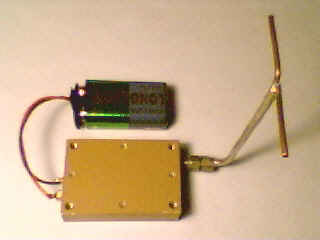
How about a super-low-cost 2.4 GHz signal source to help you optimize your dish feed or helix antenna? How about less than 5$ for it all? How about a unit barely larger than a 9V battery? Then, stick with me...
Doing S-band (2.4GHz) communications is often seen as technically challenging. Test equipment at microwave frequencies is hard to get and is not part of a typical ham shack. "Poor man" approaches are the best way to keep costs down and still have fun experimenting. Also, commercial equipment is usually heavy and does not offer much portability.
What made me try this solution
was the need for a cheap, portable 2.4GHz source for optimizing the
position of the helix feed on my 2.4GHz offset dish.
CIRCUIT DESCRIPTION
What I am suggesting here is
achievable by almost anybody who owns a soldering iron. It involves the
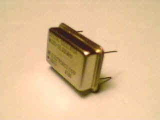
use of a computer TTL oscillator. It can be purchased at any electronics
supplier chain at a price of around 3$ (US). This type of oscillator
produces a "rather square" wave, thus an output rich in harmonics.
I elected to use a 40MHz oscillator. Its output generates signals at 40,
80, 120, 160, 200...440...1200, 1240, 1280,...2320, 2360,
2400, 2440...MHz. Of course, as you go up in frequency, the amplitude
of the harmonics decrease. 3GHz is probably the maximum useable frequency.
The circuit schematic below illustrates how simple this source is.
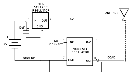
The TTL oscillator used is a leaded component. A surface mount oscillator can also be used. Connections will be done on the component pads. Also, other oscillator frequencies can be used if harmonics on different bands are desired.
A +5V voltage regulator is used here to ensure that the oscillator is supplied with +5V regardless of the battery voltage. The battery or supply could ultimately go up to +35V and this circuit would still operate. Make sure you use a decoupling capacitor at the input of the regulator, as shown on the schematic. During testing I neglected to put one and the voltage regulator operated erratically. Pick a capacitor that will sustain the input voltage. The minimum voltage that will make the source operate is around +7V.
CONSTRUCTION
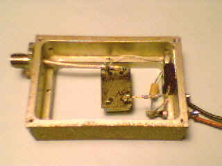
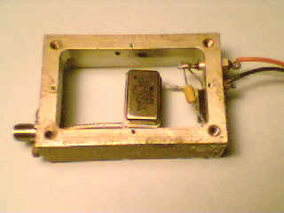
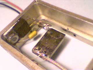
To contain my circuit, I used
an old RF module enclosure from which I stripped off the PCB. I only retained
the feedthrough capacitor for the voltage supply and the SMA connector
and coax cable. You can use other types of metal boxes. You can also use
other types of coaxial connector. BNC and N-type are other good choices.
Nothing is really critical here in terms of construction technique for
this unit to work. During initial testing, I had the oscillator lying on
its back on the workbench with only an alligator clip jumper wire as the
antenna. No coax, no casing, and it worked!
Nevertheless, there are a few
things you may want to do to make it more reliable and efficient. You will
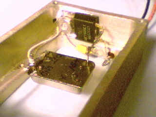
want to bring out the RF signal to the connector through a piece of coaxial
cable, or directly solder the output pin (8) of the oscillator to the RF
connector. Solder the coaxial cable as close to the oscillator case as
possible without touching it. Cutoff the excess lead protruding past the
connection. Also solder the coaxial shield to the GND pin (7).
Also, temperature regulation
is a key factor for frequency stability. A sealed metal box will give better
results as it adds inertia to temperature variations outside of the enclosure.
It is best to mount the voltage regulator against the casing to dissipate
the heat away from the oscillator. Also, I mounted the oscillator in suspension
inside the enclosure, not touching any side of it.
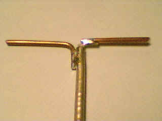
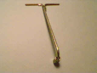
For an antenna, you can use a short piece of wire. I am a perfectionist, so to improve signal radiation and attenuate undesired harmonics I also built an accompanying 2.4GHz dipole antenna. I used a piece of UT-141 semi-rigid coax cable connectorized at one end. I built the dipole using 2 pieces of 3.5cm long #14 AWG copper wire soldered to the tip of the coax (see photo below). I trimmed the wires to optimize the return loss and ended up at 17dB with 3.1 cm on both sides of the dipole. Construct the antenna using the latter dimention and you will be close enough for good performance.
OPERATION
After powering up the unit,
let it run for 5 minutes to allow it to stabilize in frequency. Once stabilized,
the 2.4 GHz signal is stable enough to allow you to work for several minutes
without having to retune the VFO on your radio.
While testing in the basement,
I picked up a S7-strength signal at 25 feet using a 16-turn helix connected
to my downconveter. This is plenty of RF for antenna optimization!
This circuit only draws 20mA
from the 9V battery, so many hours of operation can be expected with a
fresh battery.
The unit generates +5dBm (3mW)
of RF when terminated into 50 ohms. This includes the fundamental frequency
and all harmonics.
A few points to remember:
- Do not connect this source directly to a receiver or converter. You will damage the radio front end since the amplitude is much too large (~ 3V swing at 40MHz). You must use an in-line attenuator. I recommend a minimum of 50dB of attenuation.
- Be careful as this source is not AC-coupled and has a DC bias present at its output. Connecting it to an antenna is fine, but connecting it to another eletronic apparatus may not. In this case you can add a surface-mount chip capacitor in series with the oscillator output.
- In some applications where the out-of-band filtering of the device under test is not good, spurious images could be created by other harmonics generated by this source. This could cause unexpected behavior, overload or false reading of the device under test. In this case you might want to connect a bandpass filter at the outpout of the source to select only the frequency you want.