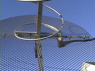
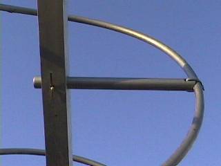
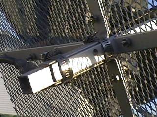
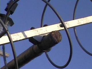
"Homebrew" 435MHz 12-turn Helix Antenna
Par/By: Bertrand Zauhar, VE2ZAZ.
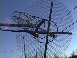
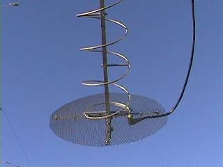
The gain of this antenna is estimated at 13dBi.
This section is presented to
give you ideas on how to achieve a sound mechanical construction, instead
of giving you an exact recipe to follow.
I used the following dimensions
for construction:
|
|
|
|
|
|
|
|
|
|
|
|
|
|
|
|
|
|
| Coupling strip
width : |
|
|
|
|
|
|
|
|
|
|
The following materials were used to build the 12-turn helix:
- Aluminum: 3/4 inch square boom, reflector arms,
- Fiberglass: Spacers ( recycled bicycle flag poles cut to right size),
- Galvanized iron: Reflector Mesh,
- Copper: The helix wire (actually 1/4" flexible plumming pipe), the PCB strip for feedpoint matching,
- Stainless Steel: All the hardware, no exception!
Assembly Notes:
- The boom is drilled through at every 1.5 turn to fit the fiberglass spacers.
- The spacers are drilled through and carved to support the copper tubing at one extremity. They are also drilled so that they can be fasten to the boom at the other extremity.
- Stainless steel cotter pins are used to fasten the fiberglass spacers to the boom. The cotter pins are inserted through small holes made in the boom and in the spacers.
- I painted all copper and fiberblass surfaces with polyurethane-silicone alkyd paint.
- The coax cable used at antenna: 6 feet of Belden 9913, connecting 45 feet of best quality coaxial cable.
- The connector used: N-Female, panel mount type, housing soldered directly to reflector mesh, center pin soldered to helix wire.
- The reflector is designed so that it can be moved back and forth for SWR tweaking. Two hose clamps hold it in place when finished.
The final SWR adjustment
is performed by sliding the reflector assembly. The N-connector center
pin, lenghtened by a piece of AWG 12 gauge wire, is fed through a hole
made in the helix tubing, but is not soldered to it. Center pin is only
soldered to helix tubing when completed.
For more information on the helix antenna, please refer to the following reference books available at http://www.arrl.org
- ARRL Antenna Book,
- ARRL Handbook,
- Satellite Experimenter`s Handbook
