LOW PASS FILTER
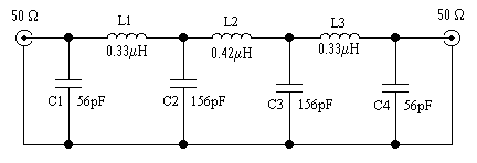
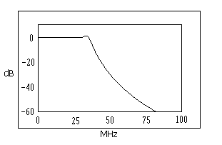
This simple 7 element, Chebyshev low pass filter, rolls of at 30MHz. Attenuation is better than -40dB at 60MHz, -65dB at 90MHz, -80dB at 120MHz.

LPF

FREQUENCY RESPONSE PLOT
The filter is housed in a box made from double-sided PCB. The input/output connectors are SO239 sockets. The usual, single hole mounting type tends to twist when unscrewing the PL259 plug. Try to find some bolt mounting sockets. The air-core inductors were wound from 1mm diameter copper wire, stripped from some 75 Ohm tv co-axial cable, details below:
L1, L3 6.25 Turns, 0.5in (12.75mm) inside diameter, 0.5in (12.75mm) coil length.
L2 8 Turns, 0.5in (12.75mm) inside diameter, 0.73in (18.25mm) coil length.
C1, C4 56pF Silver Mica.
C2, C3 100pF in parallel with 56pF Silver Mica.
The capacitors should be rated for several hundred volts. I didn't try it, but you may be able to make the capacitors from double-sided PCB.
When the filter is assembled, you can fine-tune the inductor values by adjusting the turn spacing. Use your transmitter, SWR meter and a 50 Ohm dummy load. When the filter is aligned correctly, you should have a low SWR on all bands. This filter should have a maximum SWR of about 1.1 : 1 , I couldn't get it as low as this, on all bands.
3.75 MHz 1.25 : 1
7.05 MHz 1.15 : 1
14.2 MHz 1.10 : 1
18.1 MHz 1.10 : 1
21.3 MHz 1.15 : 1
28.8 MHz 1.25 : 1