50MHz 500W IRF510 based Amplifier
This amplifier project was based on a prototype circuit developed for the HF-bands by OZ3SW, Steen Møller. The HF project was eventually scrapped because of widely varying gain from 160m to 10m.
It looked sufficiently interesting, for me to mature the basic circuit design into a singleband 50MHz amplifier.
The basic building block is a 4+4 push-pull configuration, biased at 500mA, delivering 250W out for 10W in at 40V/10A. To make life easy on yourself, use devices from a single batch, as these are most likely to be closely matched. I've used devices from Intersil (Fairchild). These are no longer being produced, but there should be an ample supply in the distribution channels. The FQP7N10 device looks to be a very suitable (and somewhat better) alternative, but have not (yet!) been tested, one interesting comparison would be IMD3 figures! I'm currently trying to obtain sample devices to build a test amplifier.
The individual IRF510s are mounted on the heatsink using Aluminium Oxide heat-transfer isolation bricks and silicone grease, for sufficiently low coupling between the MOSFETs and the heatsink to insure stability.
The input transformer (9:1) uses 4C65 cores, and the output transformer (1:4) uses thin air!
L4 is just a choke, and thus fairly uncritical, a couple of turns of the supply wire on any available piece of ferrite, see the photos, it's just
below the eletrolytic cap. on the module photo.
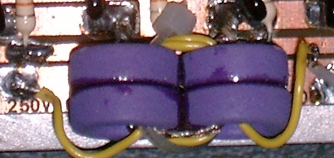
T1 is made by threading a piece of wire three times (the primary) through a piece of coax outer conductor (the secondary) around four 4C65(*See note below
on core material) cores glued together using Cyanoacrylate (Superglue), thus
creating a 9:1 impedance transformation and a very reasonable input match.
See also fig. 4 & 5 in AN749
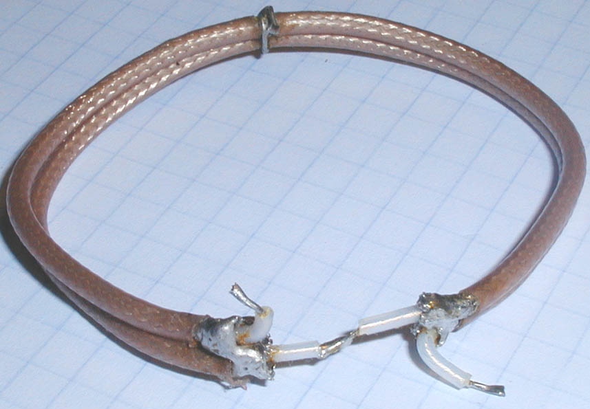
The output transformer is made from two pieces of teflon coax (RG316) 14.5cm
in length, the outer conductors joined at the middle and the ends, for the primary, and the inner conductors in series as two windings (the secondary)
giving a 1:4 ration and a close match to 50 Ohms (fine tune with C41), the B+
supply must be as near the midpoint of the primary as possible!
*I've used 4 x Ferroxcube core Material TN14/9/5 (4C65); Part No: 4322 020 9718
an equivalent Amidon would be Material Type 61 Part No: FT50-61
A very thorough description of construction of HF-transformers can be found in : Motorola Application Note AN749
The combiner used, is a simple 1/4lambda combiner made from 75Ohm Coax,
input splitter made the same way.
The end result is then passed through a low loss Elliptical LP filter with
a
70dB notch at 2nd harmonic and 80dB at 3rd.
Bias is 500mA pr module; IMD3 has not been measured, but reports on the band have been uniformly good.
More than 2000 QSOs have been made so far with this amp. Only mishap was during an F2 opening to NA in 2001, when i forgot to reduce TCVR output to
20W, I still made 4 and a ½ QSOs before things went avry (12 of 16 IRF510 blew loudly and smelly) These were quickly replaced (at less than 30c a
piece!) and no one ever commented on the output, despite the vast overdrive.
This event taught me never to rely on manual throttling of drive to an
amplifier - things will go wrong, and Murphy taught us that it'll happen
when most inopportune, e.g. when in the middle of a humongous pile-up for
the rarest of DXs! This amplifier now has a power attenuator built-in, to
reduce the 100W from my FT-847 to the 20W required for full output. (As do
my other amplifiers - all of them!) An added benefit is the reduction of
splatter produced by the overshoot from the tranceivers output regulator,
the more you throttle back the worse it gets - some modern tranceivers
produce spikes of more than 150W on VHF - and the FT-847 is far from the
worst of the bunch!
You can, of cause, combine an arbitrary number of the 250W modules to
obtain your desired output level, my reason for deciding on 500W was the
availability of a suitable powersupply.
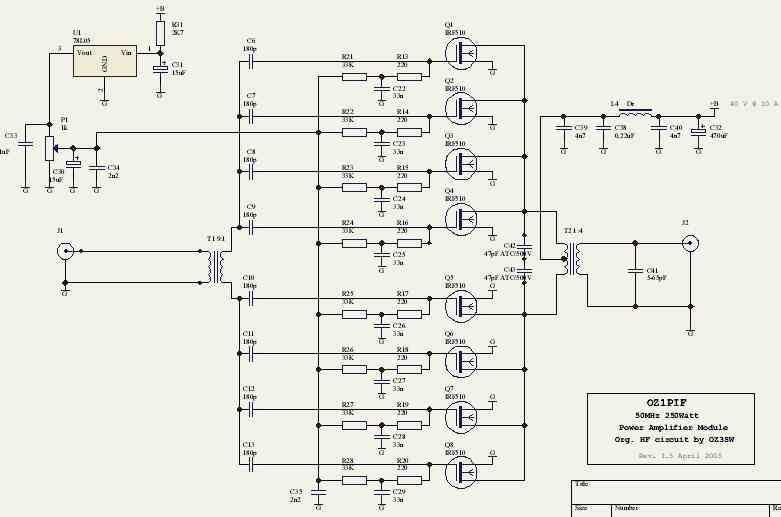
Schematic here (in PDF format)

PCB lay-out (click to obtain full resolution image), Size of PCB: 118mm x 85mm split along the horizontal line. Etched on double sided material. All drill holes for component mounting to be counter-sunk on the back-side, the rest are being used for "through plating" to connect the ground areas on both sides of the PCB.

The finished module (since the PCB design, I have added the bias circuit in the upper right corner - dead bug fashion) Click to see hi-res version. The small circuit added to the heat-sink, next to the bias circuit, is a fan-speed controller (see elsewhere on my homepage)

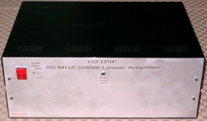
The completed amplifier (as usual click to get hi-res version)
The large finned object is a surplus commercial 800W Switch Mode PS. On top of that the Elliptical LP filter. The small PCB over the PS, contains 12- and 24V regulators and changeover relays (not seen, but cheap 20A Washing machine type, but still better than -20dB return loss at this frequency!) The grey RS-232 cable connects contol LEDs on the front to the PS.
The coils of coax cable are the splitters and combiners
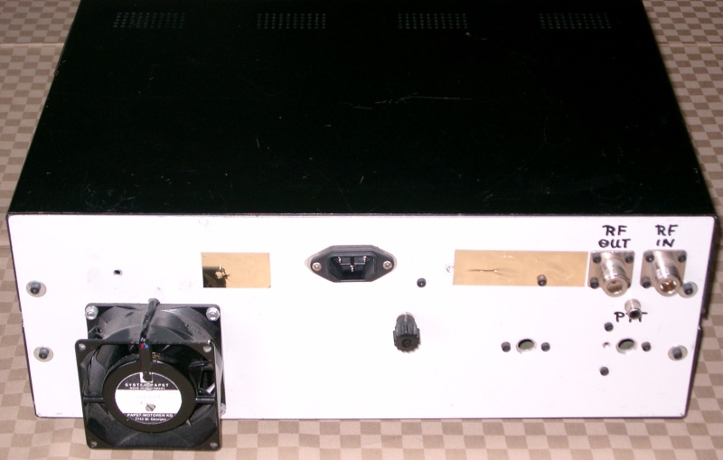
Last, but not least, the whole thing - ready to plug in - weighs just under 12.5Kg (< 30 pounds, if you don't understand metric), ideal for /P use or DXpedition travel - and that's with the present heavy duty steel cabinet, I could probably shave off another 3-4 Kg with an Aluminium enclosure.