 A SMALL LOOP ANTENNA
That is Not a Magnetic Loop Antenna
By Dr. Jef Verborgt
A SMALL LOOP ANTENNA
That is Not a Magnetic Loop Antenna
By Dr. Jef Verborgt
Over the last couple of months I have been experimenting with small loops made of coax cable, twin conductor speaker wire and pairs of twisted hook up wires. Most of my findings were published in antenneX the last three months in the Ham WorkShop corner or in my article on Small Magnetic Loops (November 2000 issue, now in antenneX Archive IV). I also exchanged numerous e-mails with Heikki Antman, OH2BGC, Dan Nesin, KQ6IA, Harold Allen, W4MMC, Joel Hungerford, KB1EGI and last, but not least, Good Old George (George Sharp, KC5MU and Senior member of the GARDS), all of whom gave me good advice and encouraged me to carry on. I enjoyed many positive reactions as well as more critical reactions pointing out the limitations of small loops due to the eternal battle between ohmic and radiation resistance. So, although I enjoyed reception of good strong signals, my quest for the holy grail was far from over. So, back to the drawing board!
 MAKING USE OF THE VELOCITY FACTOR
For several years I had tried to make shorter vertical antennas by using coax to make use
of the velocity factor or, in other words, the dielectric loading of the polyethylene
dielectricum on the center conductor which would shorten the vertical by some 34%. In the
antenna books we can all read about the coaxial vertical antenna (see Figure 1)
which works very well and is broad banded. Some scratching behind both my ears and I
decided to combine both experiences. I would put the thing in a plastic tube, coil it up
and shorten the vertical by another 3,14 % (pi) at least as far as the height is
concerned.
The theoretical length of a coaxial vertical for 14,2 MHz is 21,12meters divided by 4 or 5,28 meters multiplied by the velocity factor 0,66 giving us 3,48 meters. If we coil it up we will get a loop with a diameter of 1,10 meter or less than four feet. Before you start rushing to cut your beloved coax to that length I must warn you that, in practice, I found that a slightly longer length of about 5% was needed to get the correct resonance point. This effect might be due to a different velocity factor of the cable that I used (RG8) or to the effect of coiling up the antenna.
 Back
to Home Depot to find some suitable plastic tubing at the
correct length. I did find a translucent drinking water pipe and black irrigation pipe
both of which are sold in coils and can be bought at any length. For the connection box I
recommend again to use some of these PVC boxes which are used for wiring homes. You can
also use PVC conduit pipe which will give a direct fit to these connection boxes, it is
difficult to bend but is very solid and should resist the weather for many years. The
disadvantage however is that it is only sold in lengths of 10 feet which is some two feet
short for the 14 MHz band and extending the length is more difficult in practice than what
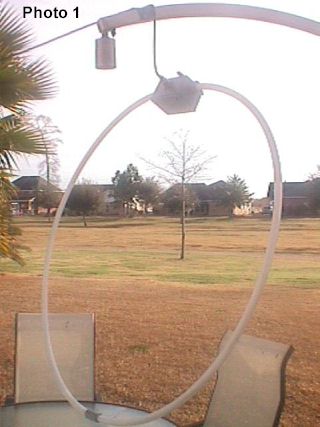
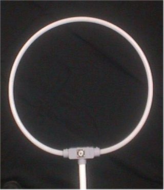
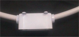
one might think. In Photo 1 (see top) you can see how the finished
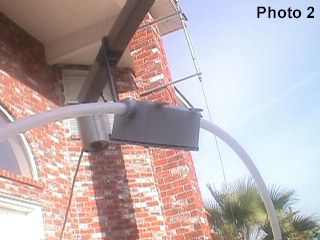
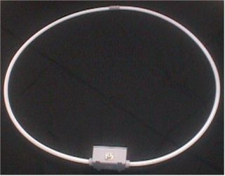
product looks. The connection box itself can be bolted to any suitable aluminum pipe or
any other support suitable of choice (see Photo 2).
Back
to Home Depot to find some suitable plastic tubing at the
correct length. I did find a translucent drinking water pipe and black irrigation pipe
both of which are sold in coils and can be bought at any length. For the connection box I
recommend again to use some of these PVC boxes which are used for wiring homes. You can
also use PVC conduit pipe which will give a direct fit to these connection boxes, it is
difficult to bend but is very solid and should resist the weather for many years. The
disadvantage however is that it is only sold in lengths of 10 feet which is some two feet
short for the 14 MHz band and extending the length is more difficult in practice than what
one might think. In Photo 1 (see top) you can see how the finished
product looks. The connection box itself can be bolted to any suitable aluminum pipe or
any other support suitable of choice (see Photo 2).
So what have we achieved so far in theory??? As this is a vertical antenna it should work close to ground level and it also should need a good ground or counterpoise to be efficient. This ground could be of a smaller dimension as the antenna itself is more compact. The antenna should also be broad banded which is the norm for coaxial antennas. The problem of the battle between the low radiation resistance and the ohmic losses has been resolved in our favour as this is not a magnetic antenna. The corresponding resonance dip for the magnetic mode of operation can actually be found at some 4,7 MHz.
USING THIS DEVICE
To put this beauty of a radiator to work we have several options:
-We can use this loop with exactly the same connections as the vertical coaxial antenna against a good ground or radials (Figure 2) or a good ground stake. Use a copper pipe of at least 6 feet in length and remember that radials usually perform better as a radio ground than a ground stake.
-We can also use the loop tuned against its coax feeder line. In this case we put a ferrite choke (I use three clamp-on ferrites) on the coax feeder at a distance of 3,48 meters from the feed point. This results in an SWR of 1,0. If we put the loop high in the air this is the most logical and economical solution and will give you very good results. It should or could beat Isotron-type antennas. This is a very economical antenna that can also easily be disguised against the shingles of a roof. You might even paint it in the corresponding colour with a can of spray paint. I did not find much directivity for this set up (Figure 3).
-If you are a great believer (and by now you should be) you could make a dipole by putting two units back to back (Figure 4). This should not be too difficult when using the PVC electrical boxes, but this time, you have to put the thing up at 1/2 of the wavelength concerned, unless mounted vertically. Once you master the art of making a dipole, the road to two and three-element Yagis with a small foot print, light weight and small turning radius is wide open for you and all with easily available PVC plumbing hardware.
-For general SWL purposes, I again did something different. I connected the ends of the loop as per Figure 5 and fed it with an autotransformer or magnetic balun with a ratio of 7 to 1. In this latter case again you are using the coax feeder as a kind of counterpoise. This set up has been performing very well for world wide reception of the amateur bands and all of this at the impressive height of three feet above the ground. Once again this set up can be used over a very large range of frequencies with an acceptable SWR for short wave listening.
For CB radio, the loop would have a circumference of 1,81 meter or 6 feet. The diameter would be 0,52 meter or well below 2 feet. Such a small antenna could be worked easily against the roof or trunk lid of a car with good results, Mounting the PVC coupling box to the car body should not present any problem provided you are not concerned about drilling holes in your vehicle. The wind load as well should not give too many problems. The connections should be made as per Figure 2. For the 10-meter band, the dimensions would be a circumference of 1.74 meter and a diameter of 0.55. Other bands can be scaled up or down easily but once again start off with a coax length slightly longer than the theoretical one.
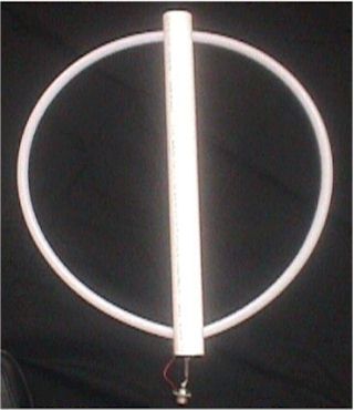
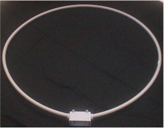
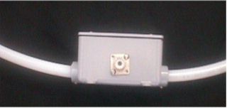
Here are some more photos of the details:
I sincerely do hope that this contribution will stimulate more experimenters to build their own antennas. It keeps you off the streets and for sure will give you a lot of satisfaction. The possibilities for people with antenna restrictions are also very good and should not be overlooked. Performance is as good as it comes for homebrewed antennas. -30-
BRIEF BIOGRAPHY OF AUTHOR
 Dr.
Jef Verborgt was born in 1944 in Belgium. Jef was saved from a certain early
death by meningitis by the American soldiers having the first penicillin for which he is
still grateful. He went on to obtain a Ph.D. degree in Polymer Chemistry in 1970 at
Louvain Belgium followed by a postdoctoral Fellowship with Dr. C.S. Marvel at the University
of Tucson, Arizona. Jef has been Director of Research for Sigma
Coatings for 15 years after which he became Director of the International
Business Operations for Marine and Protective Coatings. Jef now holds the position as
President of Sigma Coatings USA in New Orleans, Louisiana. He is
married to Marijke from Holland where Jef had lived for some 20 years. He is the father of
one daughter and two grandchildren who live in Belgium. Jef says he enjoys fishing,
Louisiana food, experimenting with antennas and living in the USA.
Dr.
Jef Verborgt was born in 1944 in Belgium. Jef was saved from a certain early
death by meningitis by the American soldiers having the first penicillin for which he is
still grateful. He went on to obtain a Ph.D. degree in Polymer Chemistry in 1970 at
Louvain Belgium followed by a postdoctoral Fellowship with Dr. C.S. Marvel at the University
of Tucson, Arizona. Jef has been Director of Research for Sigma
Coatings for 15 years after which he became Director of the International
Business Operations for Marine and Protective Coatings. Jef now holds the position as
President of Sigma Coatings USA in New Orleans, Louisiana. He is
married to Marijke from Holland where Jef had lived for some 20 years. He is the father of
one daughter and two grandchildren who live in Belgium. Jef says he enjoys fishing,
Louisiana food, experimenting with antennas and living in the USA.
Send mail to webmaster@antennex.com
with questions or comments.
Copyright © 1988-2006 All rights reserved - antenneX©
Last modified: December 30, 2005