After all the impressing results with my Magnetic Loop Antennas I was curious about the results with antennas at the other side of the L/C-Ratio: Capacitive Antennas. CAPACITIVE ANTENNAS
FOR 40m, 30m AND 20m
I came across the homepage of Arthur, DL7AHW and after some e-mails forth and back I adopted his formulas.
The components from "space" to TRX in my setup are:
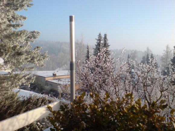
- Capacitor, aluminium household foil, 440mm high on PVC tube, 53mm diameter x 1.8m
- Inductor coil, 48 [26 for 30m, 15 for 20m] turns of solid installation wire below capacitor
- λ/4 Coax from Coil to RF-Choke, inner conductor connected to coil, sleeve open (!)
- RF Choke, 8 turns RG 174 on Amidon FT 114/43 (W1JR-style)
- Coax, any length to TRX
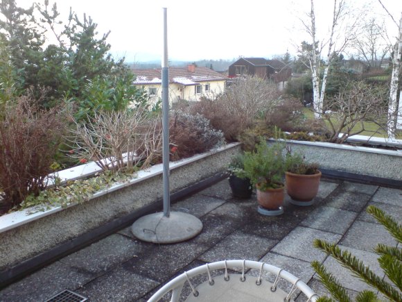
Cap-Antennas for 30m and 40m on my terrace
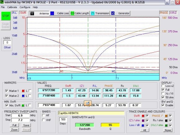
Analysis of Cap-Antenna, note excellent SWR (red line) and 1.5:1-Bandwidth (M1-M2)
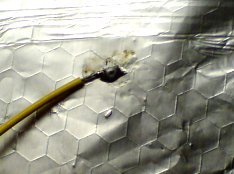
RF-Choke (RG-174 on FT 114/43) Aluminium Foil can be soldered!
Soldering of aluminium household foil
Aluminium foil can be tinned by by scratching off the oxyde layer from the foil with the well tinned tip of the soldering iron and applying plenty of tin at the same time. There is a squeaking sound like writing on a blackboard with chalk and suddently the tin begins to bond to the foil. Then any conductor can be soldered to the tinned patch on the foil. That's it!
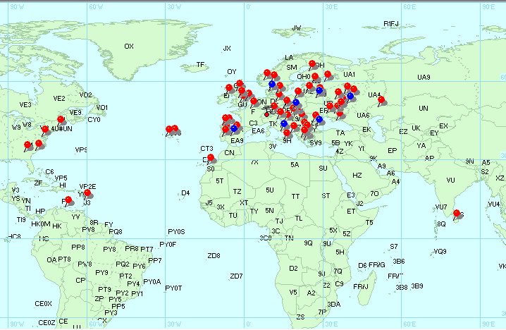
Cap-Antenna performance
My Cap-Antenna performs somewhere between a dummy-load and a full size 4-element monobander for 40m [30m], but much closer to the latter, as I never had QSO's with N2, YO, OZ, IZ8, PJ4, OM etc. with my dummmy-load!
Results with Cap-Antennas, blue = 40m, red = 30m
PSK31/63, FT897D, 25-30W, Jan. - Feb. 2009
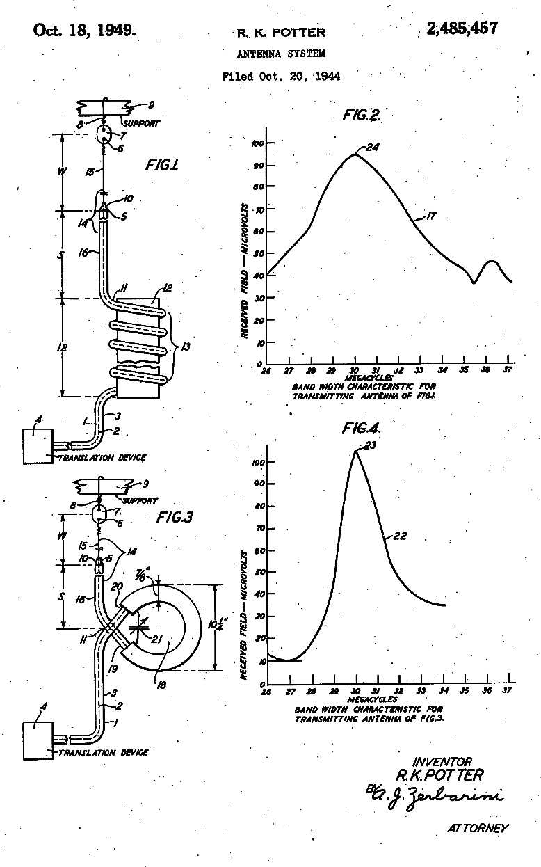
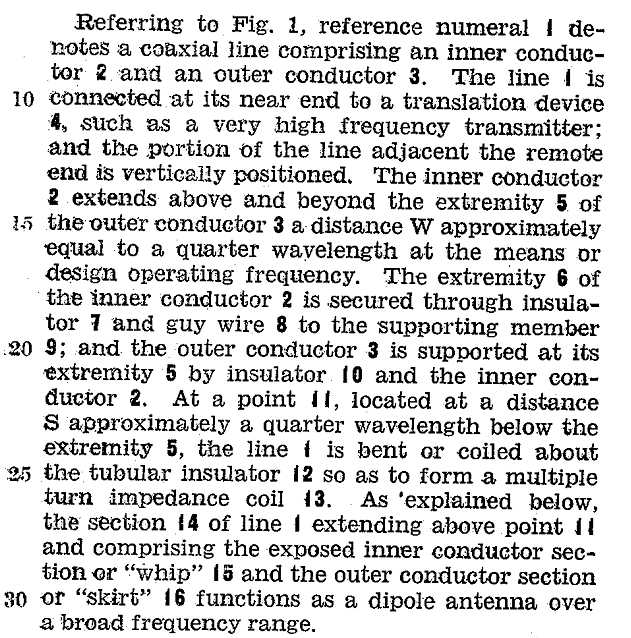
Cap-Antenna priciple
It is hard to believe, the Cap-Antenna is an end-fed dipole!
Have a look at the US Patent # 2,485,457:
The components from "space" to TRX in his setup are:
- W, upper half of dipole (in my setup λ/4 L/C-radiator)
- S, lower half of dipole (in my setup λ/4 Coax between coil and RF-Choke)
- I2/I3, RF-Choke (as in my setup)
- I, Coax, any length to TRX (as in my setup)
The arrow indicates the RF-center of the dipole (#5 in Fig.1 of the Potter Patent)
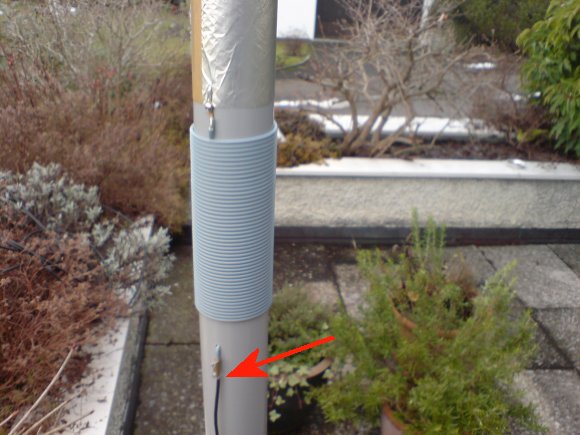
About the radiation of the open ended coax
I measured the RF-current by means of the MFJ-854 RF Current Meter and found no current at the RF choke and maximum current at the screw terminal (red arrow), as expected on one leg of a dipole. Contrary to other statements on that subject, the shield of the coax radiates!
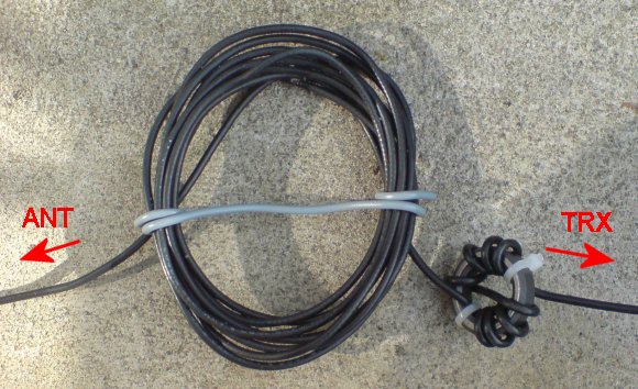
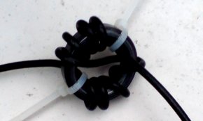
If the choke and part of the coax is laying on the ground, the coax has to be coiled up near the choke to compensate for the capacitive load.
Coiled coax at antenna side of choke
Калькулятор для CAP-ANTENNA
FORMULAS © DL7AHW
Посетите также сайт Arthur, DL7AHW
Links to Cap-Antenna sites
http://www.dk3red.homepage.t-online.de/de/s6d.htm
http://dl7ahw.bplaced.net/Superantenne00E.htm
http://www.hamradio.hr/9a4zz/
http://www.hamradio.hr/9a4zz/files/9A4ZZ%20BIPOL%20ANTENA.pdf
http://db0smg.afug.uni-goettingen.de/~dl2abc/crov/vorw.html
http://db0smg.afug.uni-goettingen.de/~dk1rm/hardware/kvert.html
This page is under construction, for more information contact: hb9mtn@qsl.net
Back