SWR mega
SWR meter design (just indicator, probe will be described later)
New version 1.1 available!
Version 1.1 (Apr 6, 2010) changes: SWR calculated using peak measured value (average value used earlier), indication of overload (too high forward power), "!!!" shown instead of SWR value.
New update 25.4.2012 Several people asked me to modify program for different LCD display sizes. Currently there is support for 2x40, 2x24 and 2x20 chars models. But I still recommend the large scale 2x40 because of best bar resolution and more text information. There is also possibility to use internal 2.56V voltage reference for ADC instead of 5V - for situation you have a probe giving max 2.56V (you must also disconnect AREF pin from +5V but keep it blocked by capacitor!). See the #if switches in source code... I publish HEX files for all display sizes for 5V standart reference voltage.
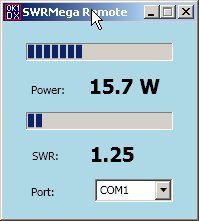
Remote display application added to package.
Goal: to build a simple circuit with following properties:
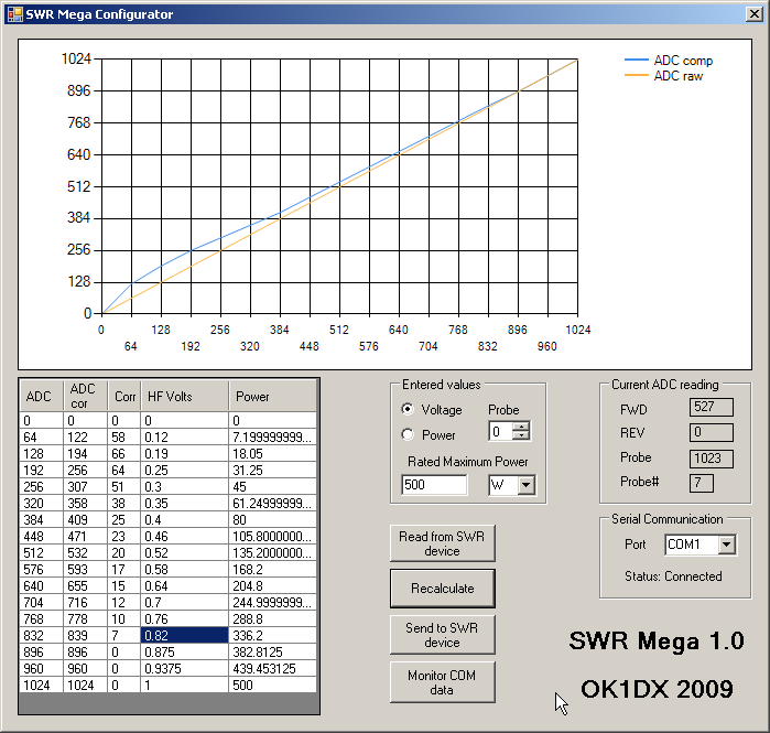
SWR and RF power meter for home usage (to be installed in Hamshack) powered from AC line or possibly from 12V DC use LCD text backlit display instead of classic analog meter bar indicators for both forward and reverse signal with maximum possible resolution display numerical values for forward power, reflected power, real power and SWR. Selection between peak or average values. possibility to use up to 8 different RF probes with different characteristics and power ranges possibility to calibrate each probe (compensation for detector non linearity) using software tool under Windows
Technical points
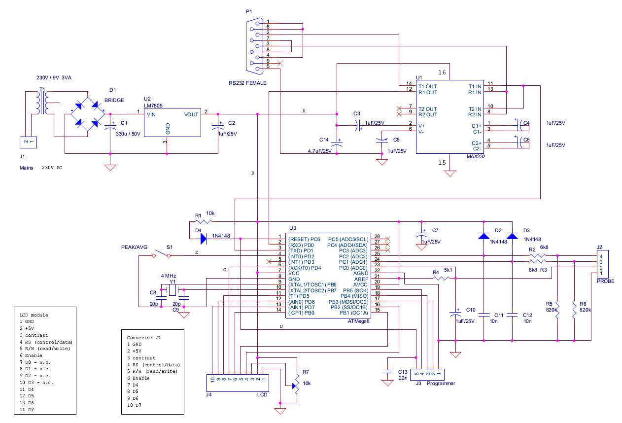
Heart Atmel AVR Mega8 single chip microcontroller - powerful, cheap, easy to get, easy programmable (without need to remove it from the circuit). Program written in C using WinAVR tools and library, free, sources available here (of course!) Use analog-digital convertor on the chip to read analog signals from probe (10 bit resolution) Use USART for serial communication (interface with well known MAX232 IC) for configuration parameters and actual measured data LCD display 2 lines 40 characters each (large, good readable). Maximum possible resolution of bar indicators reached using LCD's graphical general RAM: the top line is able to display 2 bars, each with 80 squares resolution (1 character consists of 4 squares) Probe identification using analog signal: there is one resistor in each probe; the meter supplies current and microcontroller measures voltage on that resistor. The value identifies the probe Set of parameters for each of 8 probes: maximum range (number), decimal place displayed, unit (pW till MW), correction of detector non linearity as table of 16 values for 16 equally spaced ADC values. The value between that points is calculated using linear interpolation One side PCB only, with minimum wire jumpers and without "narrow places", easily made in shack of ordinary HAM I use LCD display type Solomon LM1030SYL, 2 lines, 40 characters each, based on standard chip HD44780. I don't expect compatibility problem with other similar models. Just one experience: some product (very few) have different pin layout (esp. crossed ground and +5V), so check carefully documentation of your particual model. LCD display 2 lines 20 character each has been tested as well - the bar indicator resolution is sufficient, the bottom line shows only probe ID, power and SWR (there is a parameter in source code defining display width resulting in another HEX firmware; the EEP is the same). Probe design is not yet part of the project. Perhaps when I build a probe that I like I will publish it here as well. But - currently a lot of designs exist... The basic probe parameters: maximum voltage (full range reading) is +5V DC, the same range for reverse and forward signals. The meter is very low load for the detector, in range of 1 MOhm.
Remote display - a simple Windows application reading power/SWR data from SWRMega over serial port.
Documentation
Manual
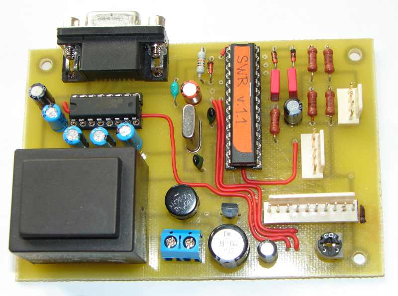
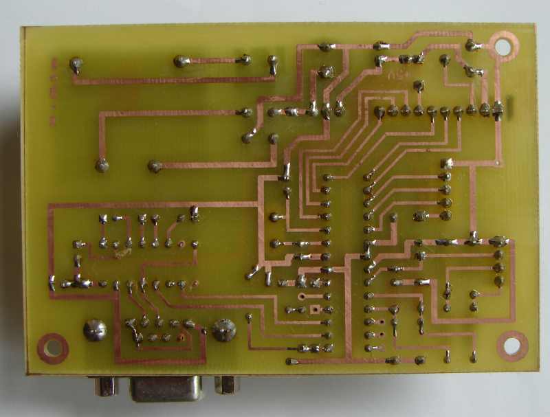
Printed circuit board layout
Source code in C language
Complete user package for download: manual, binary files, programming tool, calibration tool, remote display, PCB layout files, size 2 MBytes
Complete developer package for download: C sources for AVR, PCB layout sources (ExpressPCB format), C# sources for calibration tool and Remote display(MS Visual Studio 2008)
Supporting package for download: Microsoft Chart component (free, used in calibration tool; .net framework 3.5 SP1 required), ExpressPCB setup for PCB layout, total size 11 MBytes
WinAVR 13.3.2009 development tool size 22 MBytes (GNU license) for Windows
One SWR probe not a complete design, more how to design
Very first obsolete version 1.0 sources and binaries. Just for sure...
Links
Atmel home page for AVR microcontrollers
ExpressPCB, free PCB software and PCB production
Support
The project is hamware, free for radio amateurs and non commercial usage (that means, to build one copy for you, not for sale). For all other purposes please contact me.
I have an experience some HAM's ask me for help to get the microcontroller, to program it etc. I try my best to help them, but it is just a hobby and I have limited resources... About the PCB - I have no possibility to produce the boards. Anyway, if you are in position you can arrange the PCB for others, please let me know and I will publish contact to you here.
73 Pavel OK1DX
Clones
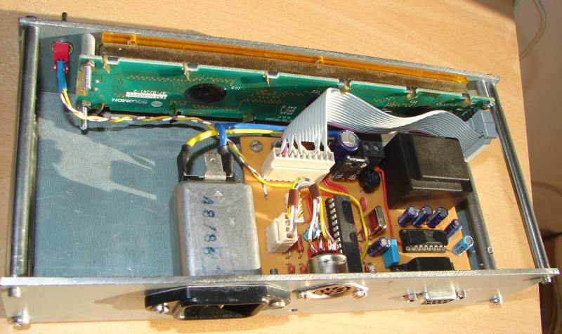
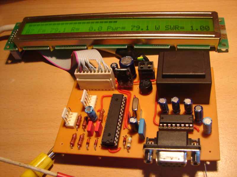
I have built another piece for my club station, here are the pictures:
Don't forget to connect the display correctly (pins D0-D3 not connected)!

