Steppermotor controller with ATtiny13
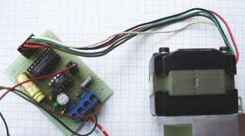 This application of an AVR demonstrates controlling a steppermotor with an ATMEL ATtiny13, with the
following properties:
- Designed for cable drive remote steppermotors with a gear unit.
- An input voltage between 0..5 V with a resolution of 10 bits (1024 voltage steps, 4.88 mV
per voltage step) controls the position of the steppermotor.
- Number of steps of the motor can be adjusted to up to 65,535 steps, so any gear unit and number
of rotations of the motor can be selected by software.
- Simple driver for driving the motor.
- Very fast rotation of the motor can be achieved by optimizing the drive frequency.
- Reduction of current requirements by switching the coils of the motor off after a preselectable
activation time following the last step.
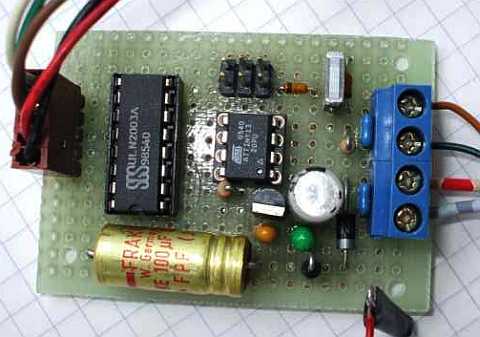 The hardware consists of the AVR processor ATtiny13, a six pin standard
programming connection for In-System-Programming (ISP), the 7-bit driver
ULN2003, the supply for the processor and the filtering of the analogue
input signal. The schematic diagram (click on it for a PDF page with higher
resolution):
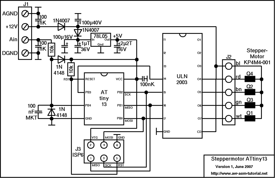 The processor ATtiny13 provides the following functions.
The operating voltage of 5 V is supplied to the pins 8 (+5 V)
and 4 (0 V) and blocked with a ceramic capacitor of 100 nF.
Pin 1 (= RESET input) is tied with a resistor of 10 kOhm to the
operating voltage.
Input PB4 (Pin 3) measures the analogue voltage, using the internal
AD converter, by comparision with the operating voltage. From its conversion
results, software calculates the target value of the steppermotor's steps.
The output port pins PB0 to PB3 (pins 5, 6, 7 and 2) control the driver for
the coils of the steppermotor.
The ISP interface serves as programming interface to program the AVR in the
system. The pinout is ATMEL standard.
The ISP interface uses the port bits PB2 (SCK, Pin 7), PB1 (MISO,
Pin 6), PB0 (MOSI, Pin 5) and the RESET at Pin 1. The
operating voltage at VTG, if connected, provides supply current to the
programmer. Leave VTG open if the programmer provides its own supply.
GND is reference for the negative operating voltage.
The drive current for the coils of the steppermotor is controlled by
the driver IC ULN2003A. The outputs with open-collector-driver transistors
allow for voltages of up to 50 V and currents of up to 500 mA.
They switch the different coils of the motor on aned off.
Induced inductive backdropping voltages, when coils are switched off,
are shortcircuited by diodes, that are connected internally from each
collector to the pin CD. The motor used here is operated with a 12 V
supply voltage and requires a current of approx. 150 mA per active
coil (because there are alway two coils active at a time, together
300 mA).
The input pins I7..I4 of the driver are controlled by the processor
(active high, logic 1 switches coil on).
The supply voltages are filtered to avoid glitches by the switching
coils. Supply of the coils is connected over a diode 1N4007 and
smoothed by a capacitor of 100 µF.
The processor is supplied by a voltage stabilizer 78L05. Its input
is connected to the 12 V supply over a diode 1N4007 and and
capacitor of 100 µF. The stabilizer is blocked with
tantalum capacitors of 1 µF resp. 2,2 µF to
avoid oscillations.
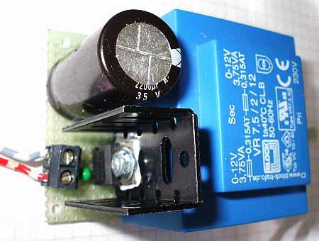
The supply and regulation of the controller/driver comes over a
four-wire connection cable from a 12 V power supply
(click on the picture to download a PDF doc with higher resolution).
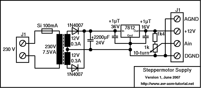
The 12 V supply is mounted on a small board.
 The software for the ATtiny13 is written in assembler, the source
code is here for download.
The software consists of the following basic elements:
- the Reset- and Interrupt vector table,
- the initialization of the starting values and the hardware
components,
- the AD conversion of the input voltage,
- the calculation of the target value from the measured voltage,
- the step control and output to the steppermotor.
Reset- and interrupt vector table
The vector table redirects program execution to the main program, if a
reset starts the processor. In case of an interrupt, the service routines
for the timer/counter and the AD converter are re-directing. Available
vectors that are not used here are represented by RETI instructions.
Init of start values
Initiation of start values is coded starting with the label "Main:".
Here
- the stack is initialized, because interrupts and subroutines are used,
- the flag register is cleared (see more about its function below),
- the registers holding the target and actual value of the steppermotor
are cleared,
- the deactivation counter is set to its initial value.
Init of the hardware
Initing the hardware consists of:
- the direction of the four portbits PB0 to PB3 are set to be output
and these bits are set to the first step of the motor,
- the AD conversion counter is set to 64, the sum value of the conversion
result is cleared, the digital input driver if channel 2 at PB4 is
switched off (the PB4 pin is used exclusively for analog AD conversion),
the AD mux is tied to channel ADC2, and the AD converter is inited with
the following settings:
- reference voltage is the operating voltage of the ATtiny13,
- clock divider =128, at 1.2 Mcs/s internal clock and
13 clock cycles per conversion each conversion requires
1.387 ms, summing up of 64 conversion results yields a complete
measuring cycle each 88.75 ms or 11.3 measuring cycles per second.
- Interrupt after each complete conversion,
- no automatic restart on conversion complete (restart is performed in the
interrupt service routine).
- the timer/counter TC0 is set to normal CTC mode (clearing the counter when
the compare value is reached), with the following settings:
- the duration of a CTC cycle is as long as the output signal for a
single step ot the motor should last, this is controlled by the constant
cCmpA, that is written to the Compare register A of the counter,
- at the end of the CTC cycle an interrupt is triggered, the
Compare-Match-Interrupt A is enabled,
- the clock prescaler is set to 1024 and the timer is started, the
counter clock is therefore 1.2 Mcs/s / 1024 = 1.172 kcs/s,
with CTC values between 1 and 255 yield frequencies between 1172 and
4.6 cs/s for the steps of the motor.
- the processor is set to sleep mode idle, that means: between the
interrupts of the counter and the AD converter program execution is
stopped.
AD converter measurements of the input voltage
The AD converter converts the input voltage on pin 3 (PB4, ADC2)
to a value between 0..1023 and triggers a Conversion Complete Interrupt.
The Interrupt Service Routine, starting at the label "AdcInt:" reads
the result from the ports ADCL und ADCH and sums it to the register
pair rAdcH:rAdcL. The counter rAdc is decreased by one. If rAdc
reaches zero, the sum value is copied to the register pair rAdcRH:rAdcRL,
the sum is cleareed, the counter is again set its initial value 64
and the flag bAdc in the flag register is set to one. Finally, the next
conversion is started.
Summing up 64 conversion results results in an averaging over these
values, removing random results and fluctuations in the input signal,
and slows down the measuring process to a convenient cycle duration.
The resulting sum value is between zero and 65,535 (0x0000..0xFFFF),
an excellent basis for the following calculation of the target value.
Conversion of the measuring result to the target value
If after waking up the processor and exection of the interrupt service
routine the flag rAdc in the flag register is set, the conversion
routine starting with the label "AdcRdy:" is called. This routine
- clears the flag bit again,
- copies the sum value to the register pair rAdcCH:rAdcL,
- multiplies the sum value with the constant cSmSteps (the
number of forward steps for the fullscale operation of the motor)
to yield a 32-bit result,
- rounds the lower 16 bits of this number,
- divides the 32-bit result by 65,536 (by ignoring the lower 16
bits), resulting in the target value as 16 bit number, and
- writes this result to the target value register pair rSmSH:rSmSL
(during which interrupts are disabled to avoid errors in the
motor adjustment, should there be a timer interrupt between
copying LSB and MSB).
Step control and output to the motor
The step control and output to the steppermotor is done in the
interrupt service routine of the counter, starting with the
label "Tc0IntCA:".
First, the actual and the target value registers are compared.
If they are equal, a jump to the label "Tc0IntCA0:" is executed.
There, the delay counter in the register pair X is decreased by
one. If the delay counter reaches zero, the coils are de-energized
by writing zeroes to the driving port bits, the delay counter is
restarted and the service routine is left.
If the actual and the target value are not equal, the actual
value is incresed or decreased. This new value is translated
like follows to a new value for the stepper driver:
- the two lowest bits of the (new) actual value are isolated, and
- are added to the start address of the table "SmTab:" in Z,
that points to the respective table in the flash memory,
- with the instruction LPM, the byte at that address is read
to R0, and
- this is written to the output port, which switches the
correct coils of the motor on/off.
The table "SmTab:" with the two words 0x0605 and 0x090A determines
the step sequence of the steppermotor as follows:
- Step 1: 0x05, binary 0 1 0 1,
- Step 2: 0x06, binary 0 1 1 0,
- Step 3: 0x0A, binary 1 0 1 0,
- Step 4: 0x09, binary 1 0 0 1.
Note: If the coils Q1..Q4 of the stepper are connected in a
different manner to the driver outputs, it is necessary and
sufficient to change these two words (see below).
In the service routine finally the delay counter is restarted,
to keep the coils activated for the appropriate preselected time,
after changing the output pattern.
In the assembler source code, the following adjustments must/can
be made prior to assembling the code:
- The three debug switches debug_calc, debug_const and debug_out
must be set to zero!
- The constant cSmSteps should be adjusted to the number of
steps that the motor should perform over the whole range
(maximum: 65,535).
- The constant cSmFreq must be adjusted to the frequency that
the motor is reliably moving (minimum 5 cs/s - for
extremely large motors, maximum 1171 cs/s - far too fast
for most types of motors).
- the constant cSmDelay sets the number of cycles, for which
the coils stay activated, after having changed the drive
pattern of the motor. If cSmDelay is equal to cSmFreq, the
delay is exactly one second.
The order of the four coils on connector J2 might be different
with different types of motors. If a different order is to be
adapted, it is sufficient to change the table SmTab:.
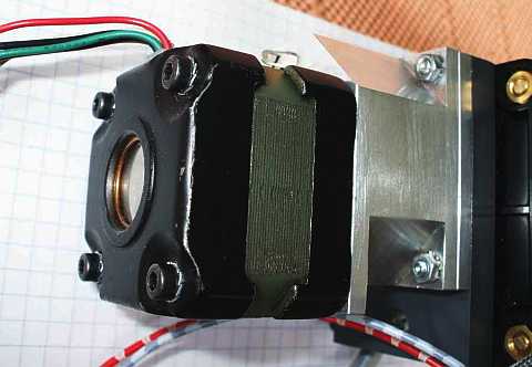
The current table is made for a KP4M4-001 type and is
generated as follows:
| Coil | color | Portbit | Step 1 | Step 2 | Step3 | Step 4 |
|---|
| Q1 | red | PB3 | 0 | 0 | 1 | 1 |
| Q2 | green | PB1 | 0 | 1 | 1 | 0 |
| Q3 | brown | PB2 | 1 | 1 | 0 | 0 |
| Q4 | white | PB0 | 1 | 0 | 0 | 1 |
The resulting table code is as follows:
| Step | Coil | Portbit | Byte | Word |
|---|
| Q4 | Q3 | Q2 | Q1 | PB3 | PB2 | PB1 | PB0 |
|---|
| 1 | 1 | 1 | 0 | 0 | 0 | 1 | 0 | 1 | 0x05 | 0x0605 |
| 2 | 0 | 1 | 1 | 0 | 0 | 1 | 1 | 0 | 0x06 |
| 3 | 0 | 0 | 1 | 1 | 1 | 0 | 1 | 0 | 0x0A | 0x090A |
| 4 | 1 | 0 | 0 | 1 | 1 | 0 | 0 | 1 | 0x09 |
The source code is available in .asm text format here, in
.html format here.
©2007 by http://www.avr-asm-tutorial.net
http://www.avr-asm-tutorial.net/avr_en/APPS.html
This application of an AVR demonstrates controlling a steppermotor with an ATMEL ATtiny13, with the following properties:
The hardware consists of the AVR processor ATtiny13, a six pin standard programming connection for In-System-Programming (ISP), the 7-bit driver ULN2003, the supply for the processor and the filtering of the analogue input signal. The schematic diagram (click on it for a PDF page with higher resolution):


