Логический минианализатор на 4 входа
Василис Серасидис
http://www.serasidis.gr
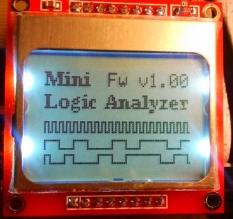
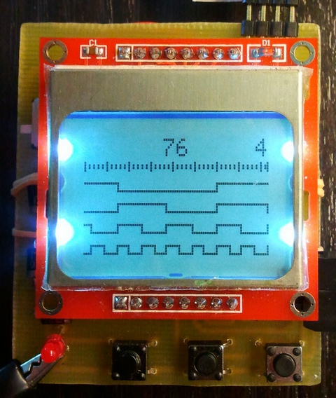
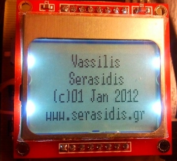
Рис.1-3. Информация на дисплее.
Функции Частота захвата Напряжение логических входов
Источник питания
ЖК-дисплей (LCD)
Захват сигналов длины:
400 кГц до +5 В постоянного тока.
Максимум 4,8 В постоянного тока (4 аккумулятора по 1,2 В)
Nokia 3310/5110 (84x48 пикселей)
От 3,7 мс для высокоскоростных сигналов до 36 с для низкоскоростных сигналов
Введение
Этот мини- логический анализатор представляет собой инструмент для просмотра на ЖК-дисплее логических переходов 0 или 1 цифрового сигнала данных. Сигнал цифровых данных можно найти на выходном контакте инфракрасного приемника TSOP-1730, на контактах передачи и приема микросхемы MAX-232 (RS-232), на контактах Clock и Data шины данных I2C и на многих других электронных компонентах. Эта схема поддерживает захват цифровых сигналов частотой до 100 кГц.
Описание
Рис.4. Схема анализатора.Рабочее напряжение схемы 4,8В постоянного тока от 4х1,2В аккумуляторных батарей. Включите S1, чтобы включить электронную схему. После первых экранов на ЖК-дисплее вы увидите сообщение о том, что AVR ожидает изменения сигнала на входных контактах. AVR имеет 4 внешних подтягивающих резистора 33 кОм (R2-R5), что позволяет избежать ненужного срабатывания любого входного контакта из-за внешнего электромагнитного поля или случайного прикосновения руки к любому входному контакту. ЖК-дисплей Nokia 3310/5110 работает от источника питания 3,3–5 В. Проблема в том, что подсветка ЖК-дисплея работает при максимальном напряжении 3,3 В постоянного тока. Поэтому я поставил диоды D1-D3, чтобы уменьшить напряжение с 4,8В до 4,8-(0,7*3)=2,7В, что является необходимым питанием ЖК-дисплея Nokia. Когда вы включаете цепь, светодиод LED1 выключается. После первого запуска на любом из 4 входных контактов этот светодиод загорается, и AVR начинает захват данных в свой внутренний буфер ОЗУ (290 выборок).
ВНИМАНИЕ!!!
Не используйте вместо аккумуляторных обычные щелочные батарейки напряжением 1,5 В. Общее напряжение составляет 4 х 1,5 = 6В. Это напряжение, вероятно, сожжет ЖК-дисплей и микроконтроллер AVR.Программное обеспечение (прошивка)
Как вы можете видеть на рисунке 5, буфер данных состоит из 870 байтов (v1.00): 2 для счетчика и один для информации о входных контактах. В версии 1.01 буфер данных был уменьшен до 256*3=768 байт для увеличения скорости захвата, поскольку переменная размера буфера составляет 8 бит вместо 16 бит, которые я использовал раньше. Следующие расчеты байтов должны выполняться в соответствии с используемой вами версией прошивки.
Рис.5. Процесс сбора данных.Как это работает? Это просто.
После включения питания AVR ожидает триггерного импульса на любом из 4 входных контактов. Если обнаруживается триггерный импульс, AVR начинает отсчет времени, необходимого для следующего триггера на любом из 4 входных контактов. Длина выборки хранится в 16-битной переменной с именем «counter». Когда эта переменная переполняется, состояние 4 входных контактов и значение счетчика сохраняются в буфере, а его адрес увеличивается на 3 (2 байта для счетчика и 1 байт для данных входных контактов). Этот процесс выполняется до тех пор, пока AVR не заполнит все байты буфера (870/3 = 290 выборок или триггеров). Когда AVR заполняет буфер, все данные отображаются на ЖК-дисплее в виде графика. Вы можете переместить график влево (кнопка S3) или вправо (кнопка S4), чтобы просмотреть всю последовательность данных. Если последовательность данных идет с низкой скоростью, вы можете сжать график (уменьшить масштаб) с коэффициентом 2, 4, 8, 16, 32, 64, 128, 256, 512, 1024, 2048, 4096 или 8192, нажав кнопку S2. кнопка.Программирование ATmega8
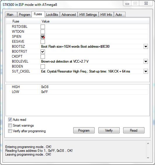
Запишите ATmega8 с помощью miniLogicAnalyzer.hex и выберите внешний кристалл в разделе предохранителей (FUSE).
Предохранители, которые необходимо установить на микроконтроллере ATmega8.
Печатная плата (55х65 мм) и размещение компонентов.
History:

04 февраля 2012 г. (v1.01)
Я сделал перекомпиляцию исходного кода с помощью AVRstudio-5 (версия 5.0.2123) и увидел гораздо лучшую стабильность захваченных сигналов. Итак, я поместил исходный код и шестнадцатеричные файлы для AVRstudio-4 и AVRstudio-5 в один и тот же zip-файл версии 1.01 .03 февраля 2012 г. (v1.01)
Скорость захвата была увеличена со 100 кГц до 400 кГц.02 января 2012 г. (v1.00)
Первоначальная версия Василиса Серасидиса .