2M CW TRANSMITTER
I use this simple CW transmitter for working through the RS13 satellite. Using just 10 Watts and a dipole at 3M above ground, I have made many contacts around Europe and across the Atlantic.
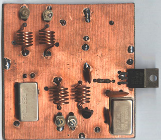
160MHz/14MHz Mixer PCB
The 146 MHz signal is generated by mixing the signal from a 14 MHz VFO with the 160 MHz output from an 80MHz crystal oscillator and frequency doubler. The oscillator is a standard 5V TTL 'oscillator in a tin can.' If you can't find a suitable 80MHz oscillator, try using a 66 MHz oscillator and a 14 MHz VFO, 66 * 2 = 132 + 14 = 146.
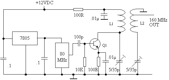
Oscillator/Doubler
A 7805 voltage regulator provides a stable 5V supply to the crystal oscillator module. The 80 MHz output from the oscillator drives a frequency doubler, Q1. The 80 MHz fundamental signal and any unwanted harmonics are removed by a band pass filter. Q1 is a 2n2369 or similar VHF transistor. L1 is 5 turns of 1mm Copper wire, 7mm Dia. The turn spacing is equal to the wire diameter. L2 is 5T tapped at 1T.
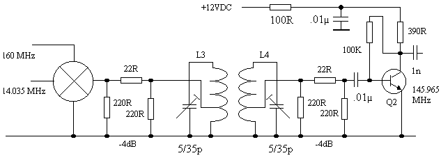
Mixer/Amp
The 160MHz signal from the osc/doubler circuit is mixed with a 14 MHz signal from a free running VFO. The VFO that I use is very similar to the VFO for the 80M SSB transceiver, see my index page for details. The mixer is an SBL1 DBM. The mixer I.F. port is terminated by a 4dB attenuator, this is followed by a 145MHz band pass filter and another 4dB attenuator. L3 and L4 are similar to L2, 5T tapped at 1T. The turn spacing is about 1.5 times the wire diameter. The amplifier, Q2 makes up for the 15dB loss of the mixer,attenuators and band pass filter. Q2 should be a UHF high gain, low noise device. I used a BFR91.
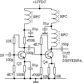
LOW LEVEL AMP
The low level amplifier increases the signal from the mixer/amp stage to several hundred mW. Q3 is a 2N2369, Q4 is a 2N4427. RFC's are 1 microHenry.
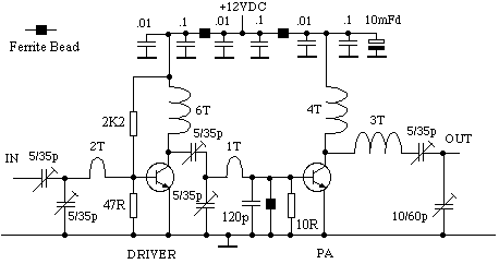
DRIVER AND PA
The driver and PA are built on one side of a rectangular piece of double-sided PCB. The board is not etched, all connections are wired point to point (Ugly Construction). The driver is an SD1012. The PA is an SRF1585. Both transistors are mounted on a heatsink. The output matching network will not give sufficient harmonic suppression. A low pass filter (see below) must be used.
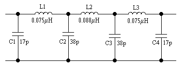
L1 and L3 are 4 Turns of 1mm wire 7mm I.D. L2 is 4.5 Turns 7mm I.D.
This is not a project for the beginner. Correct alignment of the band pass filters and matching networks is necessary to ensure that there are no spurious signals at the transmitter output.