30 WATT PA FOR 80 METRES
80M PA
Q1 and Q2 are IRF521 mosfets. The input transformer is 6 turns trifilar wound on a pair of stacked Ferrite cores. The output transformer primary is 1 turn, centre tapped, of brass tubing. I used a section of telescopic aerial from a portable radio. Perhaps I got a bit carried away, but I removed the chrome plating in an effort to reduce RF losses due to skin effect. The output transformer secondary is 3 turns of insulated wire. The transformer core is made from 6 Ferrite toroids, 3 on each brass tube. The end plates are made from single sided PCB. See "Solid State Design For The Radio Amateur" for details. Use high permeability Ferrite toroids for the transformers, initial permeability = 800 to 1000. Sorry! I don't have the part number for the toroids that I use.
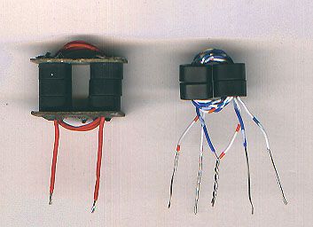
TRANSFORMERS
OUTPUT TRANSFORMER DETAIL
The mosfets should be mounted on a heatsink. For SSB/CW use, a 2 Deg./Watt heatsink is recommended. For high duty cycle modes like FM, RTTY, or SSTV a bigger heatsink will be required.
Before connecting the power supply, make sure that the bias adjustment potentiometer is set to the minimum position. Apply power and slowly increase the bias until the standing current is 200mA. If you don't have a box of spare mosfets, use a 6 Amp fuse between the PSU and the PA.
The low pass filter is a seven element version of the filter from my 80M QRP CW Transmitter tx.html
LOW PASS FILTER