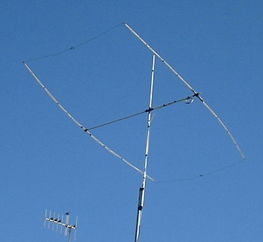
A compact 2 element beam for 10M
During a visit to a local garden centre, I bought a pack of 6ft bamboo rods. Armed with just a
couple of rolls of sticky tape, some fibreglass rod, cable ties and the pack of bamboo, I set about building
a beam for 10M. I don't have enough room for a full size Yagi or quad, even if I had, the bamboo
rods would be too short. I eventually decided to build a 2 element Yagi with the ends folded
inwards, like the VK2ABQ beam or the Moxon rectangle.
The physical dimensions of this aerial were not determined by any published formula or theory
but by the length of the bamboo rods. For the driven element and reflector, I used two bamboo rods
joined together with vinyl tape. The total length of the two rods is 3.35M (11ft). For the
boom, I used a 2.1 metre length of fibreglass pole that I scrounged from John (EI7BA).
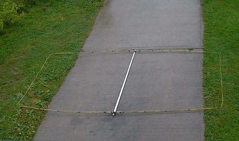
Driven element and reflector details
The bamboo elements are attached to the fibreglass boom by a criss-cross arrangement of heavy
duty cable ties. I used a pair of pliers to get a really good pull on the cable ties. After
the cable ties were tightened, I stretched several layers of vinyl tape over them.
I cut a resonant half-wave length of plastic covered wire for the driven element. The conductor
is 1.5 mm, multi-strand copper with PVC insulation. The driven element 4.95M (16.241ft)
long.
300/f = free space wavelength. 300/28.5 = 10.5263M.
divide by 2 for a half wavelength = 5.26315M.
multiply by the velocity factor of the wire (0.94).
5.26315 x 0.94 = 4.947M.
The reflector is about 7% longer than the driven element. Wire length = 5.29M. The exact dimensions
are in the diagram below. The spacing between the centre of the driven element and the centre of the
reflector is 2M (6.56ft). You can use small cable ties or vinyl tape to fix the wire to the
bamboo rods.
Exact dimensions of wire elements.
The gap between the ends of the driven element and reflector is about 175mm (7in). I used a couple
of short lengths of nylon cord as insulators. I did try pulling the wire ends closer together as
with the VK2ABQ but I found I could get a better F/B ratio with a wider gap.
The NEC2 input file is here: 10M-beam.nec
Mounting the boom on the support mast
The boom is mounted on the support mast with a cross shaped brace made from aluminium and some
more heavy duty cable ties. A length of nylon cord runs from the centre of each element to the
top of the support mast The cross shaped brace was made from a square of aluminium plate with
the four corners cut away.
I used 75 Ohm co-ax for the feeder. Ordinary TV co-ax or the double screened co-ax used for
satellite TV has very low losses at 28MHz. I made a loop of 6 turns,
150mm (6in) diameter, close to the feedpoint as a 'poor man's balun'.
Why does it always rain when I work outdoors?
The beam was placed on a 3M (10 ft) pole to do some initial tests. Most stations reported a
F/B ratio of about 3 S-units. The performance of the aerial compared with a
half-wave vertical suggests that it has some gain over a dipole. Next, I increased the height
to 7M (23ft). I spent several days experimenting with the length of the reflector and the
size of the gap between the elements. The aerial is now permanently installed at a height of
10M (33ft). The final result seems quite close to the performance of the computer model.
Most stations report a F/B ratio of between 3 and 4 S-units. Many
thanks to John EI7BA and Dick W3ORU for helping with on-air tests.
NEC2 plot in free space
The plot above shows the free space radiation pattern of the 2 element beam. The beam is optimised
for F/B ratio. It would be possible to trade a reduced F/B ratio for slightly more gain. The gain
is less than 1dB below the gain of a conventional 2 element Yagi. The F/B ratio is considerably better
than a conventional 2 element Yagi.
Graphs of gain, F/B and SWR from 27.5 to 30.5 MHz in free space.
The plot above shows the radiation pattern when the aerial is 10M (33ft) above average ground. This
plot shows a slice of the radiation pattern at 10 degrees elevation.
At 10M above average ground.
5 degrees elevation - maximum gain = 5.33dBi
10 degrees elevation - maximum gain = 9.85dBi
15 degrees elevation - maximum gain = 10.87 dBi
RP elevation plot
3D view.
The NEC2 plots and graphs were all generated by the superb 'Xnecview' software by Pieter-Tjerk de Boer
PA3FWM. This is one of the nicest open-source programs I have seen.
Xnecview homepage
Some other useful sites.
NEC Archives
W4RNL web page
EI7BA web page
References:
MODELING AND UNDERSTANDING SMALL BEAMS
PART 2: VK2ABQ SQUARES AND MOXON RECTANGLES. L. B. Cebik, W4RNL.
http://www.cebik.com/mu2a.html
'HF antennas for all locations'. L.A. Moxon G6XN. RSGB.
EI9GQ HOME BREW RADIO PAGE