Microcontroller board using the Atmel AVR AT90S8535
Richard Hosking VK6BRO
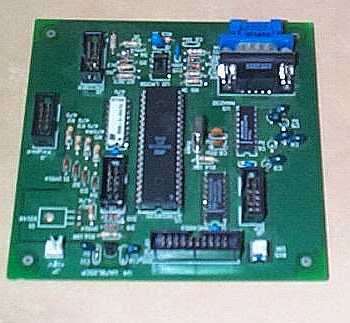
Component overlay
This board was developed to
drive a Direct Digital Synthesizer (DDS) module but could be applicable to many
situations which require a microcontroller board.
The board has a Liquid
Crystal Display (LCD) interface for common 16 character by 2
line displays, with contrast pot and power supply. There is a current source
circuit to drive a backlight at about 70 mA if required. There is an interrupt
driven interface for a 4 by 4 keypad, circuitry for a serial PC interface and a
flash programming interface to allow in circuit programming.
A rotary encoder was
required for the DDS project. There is a conditioning circuit to allow the use
of surplus stepper motors as rotary encoders. I have not explored the use of
conventional encoders with this circuit, but it would seem possible with some
adaptations.
Controller board
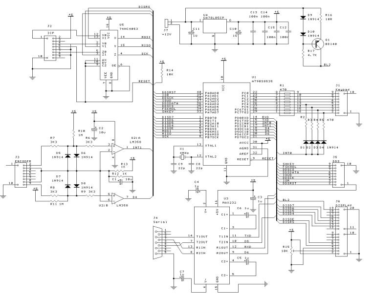
Circuit diagram of controller board
Keypad Interface
The keypad interface uses 9 I/O lines in a
conventional setup. The keypad is a 4X4 matrix with 4 inputs (either the rows
or the columns) commoned via diodes to the interrupt source INT0. The lower 4
bits of Port C are outputs with the upper 4 bits configured as inputs. The
keypad rows are connected to either the upper or the lower 4 bits while the
columns are connected to other 4 bits. A resistor pack is used to give some
static protection to the microcontroller inputs. (circuit diagram) During
normal operation bits C0-C3 are active low. When a key is pressed an interrupt
is generated via one of the 4 higher order bits C4-C7 which are configured as inputs.
The interrupt handler saves the processor and enters the keypad read routine.
In Pseudocode the keypad handler:
Disable interrupts
Save processor
Debounce key delay 20 msec
Read key by writing a low to each column in turn and reading the response.
Lookup table to return key data in Keypress
Restore processor
Enable interrupts
Return
In more detail some of the key pad source code is
shown below:
KEY1:
rcall WAIT_2msec ;
Wait about 20 msec
dec temp ;
to debounce key
brne KEY1
;
ldi temp,0b11111110 ; Column 1 low
out PORTC,temp
rcall WAIT_2msec ;
Let line stabilize
in temp,PINC ; Any key pressed?
cpi temp,0b11111110
brne KEY2 ;
If yes then save
;
ldi temp,0b11111101 ; Column 2 low
out PORTC,temp
rcall WAIT_2msec
in temp,PINC ; Any key pressed?
cpi temp,0b11111101
brne KEY2 ;
If yes then save
;
ldi temp,0b11111011 ; Column 3 low
out PORTC,temp
rcall WAIT_2msec
in temp,PINC ; Any key pressed?
cpi temp,0b11111011
brne KEY2 ;
If yes then save
;
ldi temp,0b11110111 ; Column 4 low
out PORTC,temp
rcall WAIT_2msec
in temp,PINC ; Any key pressed?
cpi temp,0b11110111
brne KEY2 ;
If yes then save
KEY2:
ldi temp_1,$31 ; Key for 1
cpi temp,0b11101110 ; Lookup table for keypad
breq KEY3
ldi temp_1,$32 ; Key for 2
cpi temp,0b11011110 ; Lookup table for keypad
breq KEY3
ldi temp_1,$33 ; Key for 3
cpi temp,0b10111110 ; Lookup table for keypad
breq KEY3
ldi temp_1,$34 ; Key for 4
cpi temp,0b11101101 ; Lookup table for keypad
breq KEY3
ldi temp_1,$35 ; Key for 5
cpi temp,0b11011101 ; Lookup table for keypad
breq KEY3
ldi temp_1,$36 ; Key for 6
cpi temp,0b10111101 ; Lookup table for keypad
breq KEY3
ldi temp_1,$37 ; Key for 7
cpi temp,0b11101011 ; Lookup table for keypad
breq KEY3
ldi temp_1,$38 ; Key for 8
cpi temp,0b11011011 ; Lookup table for keypad
breq KEY3
ldi temp_1,$39 ; Key for 9
cpi temp,0b10111011 ; Lookup table for keypad
breq KEY3
ldi temp_1,$30 ; Key for 0
cpi temp,0b11010111 ; Lookup table for keypad
breq KEY3
ldi temp_1,$2A ; Key for *
cpi temp,0b11100111 ; Lookup table for keypad
breq KEY3
ldi temp_1,$23 ; Key for #
cpi temp,0b10110111 ; Lookup table for keypad
breq KEY3
; ldi temp_1,0b00111111 ; Error ?
KEY3:
; mov temp,temp_1
sts AtKEYPRESS,temp_1 ; Store key data
Note that I have the columns and rows in reverse
order. In practice I have connected a keypad with unknown connections and
adjusted the code to produce the relevant outputs. The only constraint is that
the columns and rows cannot be mixed. Some trial and error may be required to
get correct operation.
Programming Interface
This interface allows the controller to be programmed
in circuit while power is applied. Code is developed on a PC with the relevant
software loaded (free from Atmel). At the end of the programming sequence the
controller resets and the operator can see the effect of code changes. This
greatly reduces development time for new projects.
This interface uses a data multiplexer (74HC4053)
which is controlled by the RESET input.
When RESET is pulled low the controller can be
programmed via the interface.
Three other lines (MISO and MOSI and SCLK) control
the data to and from the programming interface. When RESET is high these are
normal I/O lines.(circuit diagram). This interface can be driven from a simple
“dongle” on a PC serial port (eg see Silicon Chip Oct 2001or Dontronics
STK200). Software for programming the Atmel series chips in circuit, an
assembler and a software simulator is available free from the Atmel Website.
Serial Interface
There is a
standard RS232 serial interface using a MAX232 for voltage level setting
on the board. Software has not yet been developed for this interface but it
uses a conventional bi-directional UART pinout.
LCD interface
The board has circuitry to drive a LCD 16 character
by 2 line Liquid Crystal Display module. There is provision for a contrast pot
and a current source (Q1) to supply a backlight if required. The current can be
varied by varying R2. With the resistor at 10 ohms the current source will
deliver about 70 mA. Current can be calculated according to
I
= 700/R2 mA
Q1 requires a small heatsink at this current.(circuit
diagram). The software required to drive these modules is somewhat complicated
due to the startup routines. See the LCD article for more detail.
General purpose port
Port A is
configured as a general purpose port. Originally the board was developed to
drive a Direct Digital Synthesizer but could be used for various purposes.
General purpose port connections
Rotary Encoder Interface
Rotary encoders are now
widely used in digitally tuned radio applications to replace a traditional
tuning knob in a receiver for example. However they are somewhat expensive,
particularly if a large number of steps per revolution is required. It is
possible to homebrew optical encoders, but this is tedious and again critical
for a large number of steps. Surplus stepper motors from old floppy drives
offer a cheap alternative to a commercial encoder. Typically these motors have
two windings which produce pulses when the motor shaft is rotated. These pulses
are in phase quadrature. A typical motor
will produce 180 steps per revolution.
The pulses can be
conditioned to give two digital pulse trains, with one leading or lagging the
other depending the direction of rotation of the motor.
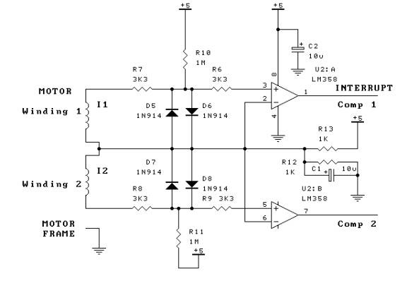
Rotary encoder front end circuit
Conditioning circuit
A dual comparator is used to
square up the outputs of the two motor windings. (Fig 6) One end of each
winding is connected to a voltage reference at half the supply voltage. (2.5V)
The other end is connected via a current and voltage limiting network to the
noninverting input of the comparator. A resistor (R7 and R8) limits current
while back to back diodes (D5-D8) protect the comparator from back EMF spikes
from the motor. The inverting input is
connected to the 2.5V reference. A small DC offset is also applied via R10 and
R11 to the inverting input to bias the comparator to one state or the other. If
a 5V supply is used the output is directly compatible with logic circuits or a
microprocessor. This circuit is sensitive enough to detect single steps at low
rotation speeds. It may be necessary to ground the motor frame to avoid noise
triggering the comparator.
The comparator outputs
are connected to 2 I/O lines on the microcontroller, with one line being a
hardware interrupt. The comparator outputs are normally high. In this case the
interrupt triggers on a low level, but an edge triggered interrupt could also
be used.
When an interrupt is
triggered the controller simply reads the state of the other comparator to
determine the direction of rotation
The controller board uses
conventional through hole components so should not present any difficulty.
(component overlay)
Controller board component overlay
There are several include
files with one main file to link these
The code is written for the
Atmel AT90S8535. The files will assemble using the free assembler from Atmel.
The In Circuit Programming
interface will work using the STK200 programmer from Dontronics.
At present the code will
drive the DDS in single tone mode with a keypad and rotary encoder for
frequency control. The step resolution is 1 Hz with a clock of 100 MHz (10 MHz on board clock multiplied by 10)
I intend to expand this to
use other modes such as sweep and digital modulation when I get around to writing
the code! Users are welcome to improve and expand the code – I would be
grateful for any feedback.
Source Code
(for personal non-commercial
use only)
This code was written to
drive a DDS (Direct Digital Synthesizer) board. However much of it would be
applicable to other situations.
Component List
Resistors 1/4W axial
1K 2 R12
R13
1M 2 R10
R11
3K3 4 R6
R7 R8 R9
4.7K 1 R17
10K 2 R14
R15
10R 1 R16
100 1 R1
470 4 R2
R3 R4 R5
Capacitors
1u tant 7 C3 C4 C5 C6 C7 C10 C11
10u tant 2 C1 C2
22p ceramic 2 C8
C9
100n ceramic 4 C12 C13 C14 C15
Semiconductors
1N914 10 D1
D2 D3 D4 D5
D6
D7 D8 D9 D10
1N4002 1 D11
BD140 1 Q1
AT90S8535 1 U1
(programmed if necessary – available from the author)
LM358 1 U2
MAX232 1 U3
UA78L05CP 1 U4
74HC4053 1 U5
Misc
PCB (available from the
author)
4MHz crystal HC9/U 1 X1
IDC box headers
10 pin 4 J1
J2 J3 J5
IDC box header
20 pin 1 J6
DB9 serial
Socket 90 deg 1 J4
2
pin 0.1 pitch
header 1 J7
References
4X4 keypad – wakeup on
keypress - Atmel app note
In system programming
– Atmel app note
Buy a board – see price list