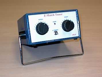
Z-Match Portable Antenna Tuner
W5JH Projects: Z-Match Portable Antenna Tuner - Sold to Gabe Sellers W2ZGB

The Z-Match antenna tuner has been around for quite a while. They were quite popular in the 1950's and currently there is a least 1 commercial version of of the Z-Match (ZM2). This tuner is known to match a wide range of antennas and also be very efficient - especially while using parallel feed lines. The picture above is one I recently built. A packet of information on the Z-Match is available from Charlie Lofgren, W6JJZ. Charlie is the guru of this tuner. If you are interested in building one for yourself, email him at clofgren@benson.mckenna.edu and ask for the Z-Match package. Some of the tuners features are:
- Broad Matching Range
- Single Fixed Coil
- 2 Knob tuning
- Dual Links (High and Low Impedance)
- Built in SWR Bridge
- High Efficiency
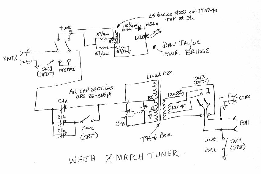
Схема
здесь.
При постройке тюнера ставилась задача получить согласование в диапазоне
7-21 МГц, поэтому индуктивность катушки была уменьшена до 1,8 мкГн, тогда как в
исходном варианте она должна быть 5,5-5,8 мкГн. Также были подключены две
катушки связи с антенной - для высокого и низкого сопротивления нагрузки, причем
L2 и L3 были намотаны симметрично относительно земляного отвода. Если вы
захотите изменить количество витков, то делайте их число кратным четырем. Такая
комбинация индуктивности и емкостей позволила перекрыть диапазон 6,8-22 МГц.
Для проверки тюнера, подключил резистор 2200 ом к выходу Hi-Z и используя
MFJ-259B измерил КСВ, который оказался равным 1,1 в диапазоне 6,5-28,5 МГц,
разумеется, после правильной настройки тюнера. Без тюнера КСВ должен быть равным
44. Затем я повторил опыт, но уже с резистором 4,7 ом, подключенным к выходу
Low-Z, результаты оказались похожими, но потребовалось подключение двух
дополнительных секций КПЕ на входе тюнера. Когда я подсоединил мою
горизонтальную "Дельту" с периметром около 52 метров, запитанную симметричной
линией 450 ом, пределы согласования у тюнера уменьшились, но тем не менее,
находились в заданном диапазоне частот.
Перевод и
подбор материалов – CКР Team© 2003.
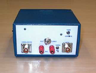
I built the Z-Match in about 3-4 days using available parts. I used a broadcast 3 section 25-365 pF cap for the series cap (C1) and a dual section 25-365 pF cap for the shunt cap (C2). I decided I wanted to use my Z-Match for 7-21 Mhz operation so I adjusted the coil L1 to give me that range. The lower frequency is determined by the maximum capacitance of C2 (365 pf in my case) and the inductance of L1. The upper frequency is determined by the minimum capacitance of C2 and stray capacitance. I plugged 365 pF into the resonance formula and calculated that I needed a 1.5-1.8 uHy coil for L1. (Note: the original L1 was 5.5-5.8 uhy) I used 16t of #22 on a T94-6 core (about 1.8uHy). The coil is center tapped at 8t (duh!) and the ground tap is at 4t. The high impedance link L2, is 8t #22 centered around the ground tap. The low impedance link L3, is 4t #22 also centered around the ground tap. (Note: If you decide to modify L1, you should keep the number of turns evenly divisible by 4.) This combination gives me about 6.8 Mhz to 22 Mhz coverage - just about right! I also included Dan Tayloe's LED SWR circuit. I built it using the island/Manhattan/paddy board/"whatever you want to call it" method. BTW, Dan's circuit works great. A Hammond Polystyrene box about 3x6x6 inches (HWD) was used to house the Z-Match. Front and rear panels were laid out using Visio Technical (a technical drawing program), printed on my color inkjet, and taped to the panels. Nylon screws and 1/4 inch nylon standoffs were used to mount the capacitors.
As a simple test, I placed a 2200 Ohm resistor across the Hi-Z balanced output and used my MFJ259B SWR Analyzer to measure the SWR through the tuner. (Note: the 2200 Ohm resistor represents a 44:1 SWR!). I was able to match the 2200 Ohm to a perfect 1.1:1 SWR from about 6.5 to 28.5 Mhz. I also repeated the test using a 4.7 Ohm resistor across the low impedance link. Again I was able to match it across the same range although I noticed that a lot more C1 is needed for low impedance loads! I had to switch in the additional two 365pF sections. When connected to my 160ft horizontal delta loop fed with 450 Ohm ladder line, the tuning range is somewhat reduced but within my original design goal.
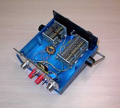
The top view. Notice the coil is held in place by its 8 flying leads.
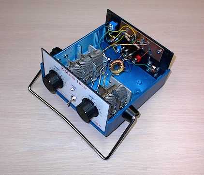
A different top view. Notice the N7VE SWR bridge is bolted to the back panel.
www.swlink.net/~w5jh/
Copyright © 1996, 1999 Jerry W. Haigwood