A Modest--But Effective--AO-10 Antenna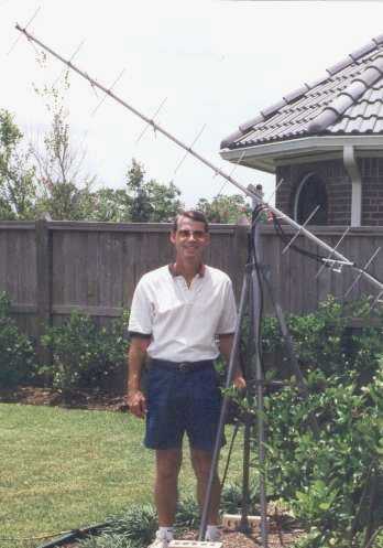
![]()
A Modest--But Effective--AO-10 Antenna
![]()
 The venerable AMSAT OSCAR-10 (AO-10) is still up there making satellite DX contacts and "rag chews" a reality for lots of amateurs. If you have been working the LEO's (Low Earth Orbit) successfully with small antennas (like me), you have probably already discovered much (much!) more gain is required to work AO-10. I have managed a few contacts using my Texas Potato Mashers as well as my first AO-10 setup--a 4-element 2 meter yagi and an 8-element 70 cm quagi with 10 Watts. However, those were marginal and all occurred when the satellite was near the horizon and closer than 12,000 km.
I longed for better "ears" and more "talk power." This is currently the only bird available for ragchews and a lot of European ops are up in the middle of the night for just that reason. Getting on AO-10 more reliably was easier than I thought and you could replicate this design with a trip to the hardware store and 4 hours of work; and be on the air that evening! For up-to-date information on AO-10, visit AMSAT and Stacey Mills', W4SM, Websites.1
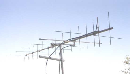
This article describes construction of a dual-band Yagi-style antenna specifically designed for AO-10 use. While I don't want to preclude use of this design for LEO's, the beamwidths are narrow enough to realistically require automated tracking for both azimuth and elevation--which I do not have (yet). The 2 meter portion consists of a stock Cushcaft VHF beam; 7 elements with an advertised 11.1 dBi gain. The 70 cm portion consists of 14 elements and has almost 16 dBi gain at 435.1 mHz. Both antennas are mounted concentrically on an 8 foot boom. This is a linearly polarized antenna and does not employ any polarization-switching schemes, but two of these could be built and set up for circular polarization and switching: see the ARRL Antenna Book or Martin Davidoff's The Radio Amateur's Satellite Handbook for examples.
Design: Several design parameters were foremost in my search for a better antenna system for AO-10. First, it needed to be inexpensive (I'm an engineer and that is often the primary design criterion). Second, it had to be small enough to be mounted on my patio-based tripod with "Armstrong" rotor--about 8 foot maximum. Third, since its service was dedicated to mode B, it needed to be optimized for transmit gain and receive S/N ratio.
The 2 meter portion of the prototype started life as a Cushcraft A144-7S I found on the Internet clearance priced for $40.2 It is 7 elements on a 7-4" boom. The original design has specifications of 11.1 dBi gain and a 20 dB F/B ratio. I confirmed this with modeling software, YagiMax, and attempted to optimize the design for an improved Front-to-Rear (considers largest rear lobe) ratio.3 This effort proved informative, but the improvement wasn't worth the extra effort (maybe later, since addition of just one more element will appreciably improve the F/R ratio). The stock dimensions are provided in Table I for those that may want to build from scratch. This is an above-the-boom design.
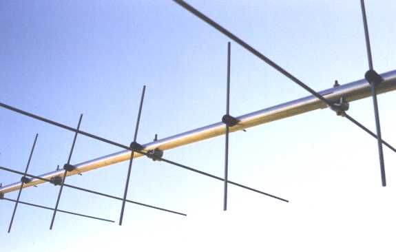 Table I: 7-element 2 Meter Antenna
Dimensions: inches (cm):
| El. | Length | Spacing | Dia. |
| R | 40-1/4 (102.25) | 0 (0.0) | 3/16 (0.5) |
| DE | 38-7/16 (97.6) | 14-1/4 (36.2) | 3/8 (.95) |
| D1 | 36-3/4 (93.3) | 28-1/2 (64.8) | 3/16 (0.5) |
| D2 | 36-1/4 (92) | 42-3/4 (108.5) | 3/16 (0.5) |
| D3 | 35-3/4 (90.8) | 57 (144.8) | 3/16 (0.5) |
| D4 | 35-1/4 (89.5) | 71-1/4 (181) | 3/16 (0.5) |
| D5 | 34-3/4 (87) | 85-1/2 (217) | 3/16 (0.5) |
The 70 cm design is optimized for transmitting. Almost the same gain could have been achieved with fewer elements on the same boomlength, but the additional elements were added to increase the feedpoint impedance-thus improving the radiation efficiency of the antenna. The design has a feedpoint impedance of about 38 Ohms, almost double the typical design. The higher radiation resistance not only improves the efficiency, it also helps flatten the SWR response curve; I note less than 1.5:1 from 434 to 436 mHz. A gamma match from an old flea market beam was used, but these are easily hand-crafted from aluminum tubing or ordered from Cushcraft as spare parts.4 See Table II for the building dimensions and Figure 2 for the azimuth pattern generated by YagiMax.
 Table II: 14-element 70 cm Antenna
 | El. | Length | Spacing | Dia. |
| R | 12-15/16 (32.9) | 0 (0.0) | 3/16 (0.5) |
| DE | 12-3/4 (32.4) | 5-3/4 (14.6) | 3/8 (0.95) |
| D1 | 11-15/16 (30.3) | 8-1/2 (21.6) | 3/16 (0.5) |
| D2 | 11-13/16 (30) | 13-1/8 (33.3) | 3/16 (0.5) |
| D3 | 11-5/8 (29.5) | 18-3/8 (46.7) | 3/16 (0.5) |
| D4 | 11-9/16 (29.4) | 25-1/8 (63.8) | 3/16 (0.5) |
| D5 | 11-1/2 (29.2) | 32-5/8 (82.9) | 3/16 (0.5) |
| D6 | 11-7/16 (29) | 40-3/4 (103.5) | 3/16 (0.5) |
| D7 | 11-3/8 (28.9) | 49-1/2 (125.7) | 3/16 (0.5) |
| D8 | 11-5/16 (28.7) | 58-1/2 (148.6) | 3/16 (0.5) |
| D9 | 11-1/4 (28.6) | 67-1/2 (171.5) | 3/16 (0.5) |
| D10 | 11-3/16 (28.4) | 77 (195.6) | 3/16 (0.5) |
| D11 | 11-1/8 (28.3) | 86 (218.4) | 3/16 (0.5) |
| D12 | 11-1/16 (28.1) | 96 (243.9) | 3/16 (0.5) |
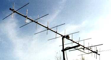
Now comes the hard part: how to put them on the same boom and minimize interaction. First, I put them at 90 degrees to each other (similar to the popular Arrow Antenna design).5 Second, knowing almost half the element current flow on the 2 meter antenna is between the reflector and the driven element, and half of the current flow on the 70 cm antenna is between the reflector and the first director, I opted to "extend" the back of the 7'-4" boom an additional 9" and place the reflector, driven element, and first director of the 70 cm antenna behind the 2 meter reflector. This effectively isolates the high-current portions of each antenna from each other, minimizing distortions to the receive and transmit patterns.
 Construction: Materials are not critical, but new calculations would need to be run if different size elements are utilized. Your mileage may vary. The boom is 8' of 1" aluminum tubing (a convenient length available at many hardware stores). The driven elements are 3/8" aluminum tubing and all the parasitic elements are 3/16" aluminum rod.6 All stainless steel hardware, size 6-32 and 4-40. (Detail)
The 2 meter elements are mounted on small aluminum brackets (Cushcraft P/N 190026). The 70 cm elements are mounted on small rubber "feet" I found at a local surplus electronics shop. There is already a hole drilled through the "bottom" of the feet for running a bolt through the boom. I carefully drilled a slightly undersized hole perpendicularly through the feet and then squeezed the 70 cm elements through the hole for a secure fit. Note all the 70 cm parasitic elements are insulated from the boom. Coating or painting the rubber is advisable to prevent UV deterioration.
Construction: Materials are not critical, but new calculations would need to be run if different size elements are utilized. Your mileage may vary. The boom is 8' of 1" aluminum tubing (a convenient length available at many hardware stores). The driven elements are 3/8" aluminum tubing and all the parasitic elements are 3/16" aluminum rod.6 All stainless steel hardware, size 6-32 and 4-40. (Detail)
The 2 meter elements are mounted on small aluminum brackets (Cushcraft P/N 190026). The 70 cm elements are mounted on small rubber "feet" I found at a local surplus electronics shop. There is already a hole drilled through the "bottom" of the feet for running a bolt through the boom. I carefully drilled a slightly undersized hole perpendicularly through the feet and then squeezed the 70 cm elements through the hole for a secure fit. Note all the 70 cm parasitic elements are insulated from the boom. Coating or painting the rubber is advisable to prevent UV deterioration.
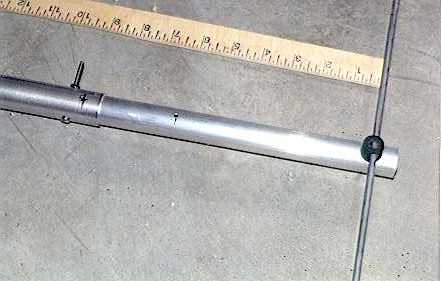 A lesson-learned on this project was in drilling the holes in the boom. If you have access to a drill press, go use it. If not, an extra hour spent carefully lining up holes on both sides of the boom and at 90 degrees is well worth the extra time. If you look carefully at the photographs, you will note I did not achieve perfect alignment of all elements on the first attempt. Another lesson worth passing on is the length of a resonant driven element "appears" shorter due to the inductive reactance from the parasitic elements. The final, resonant, 70 cm driven element is 1/2" longer than the software model prediction.
Performance: On Saturday night AO-10 was making a perigee appearance about 14,000 km out over my southern horizon, so I had my just-purchased and assembled 2 meter antenna on the same tripod as my 8-element quagi uplink antenna. I heard John, KD2JF, call CQ. We had a short QSO: I could hear him great but he had trouble copying me. No one else could hear me. That did it! On Sunday afternoon I built the 70 cm portion described above. On Sunday night, there was John again wrapping up a QSO. I called him. He said: "hey Jerry, what did you do? I have armchair copy on you." With 10 Watts, I routinely work SSB stations out to 24,000 km and have several in the log at greater than 34,000 km. A CW QSO should be possible at apogee, but I can't claim that one (yet). Next Step: get that baby on a rotator!
Epilog: While this design is specific to the stock Cushcraft antenna I had available, the concepts of concentric boom arrangement and separation of driven elements can be applied to any number of elements. The current Cushcraft "economy" model is a 10 element design on a 12' boom (A148-10S, rated at 13.2 dBi gain). Extrapolating this design to that boom, yields a 17 element 70 cm antenna with over 17 dBi of gain!
1. www.amsat.com and www.cstone.net/~w4sm/AO-10.html.
2. www.RadioDan.com, Fresno, Ca.
3. Lew Gordon, K4VX, YagiMax 3.46.
4. www.Cushcraft.com, Manchester, NH.
5. Allen Lowe, N0IMW, http://members.aol.com/arrow146/index.html
6. 3/8" tubing and 3/16" rod available from Texas Towers, Plano, Tx.
(C) 2000, Gerald R. Brown, K5OE