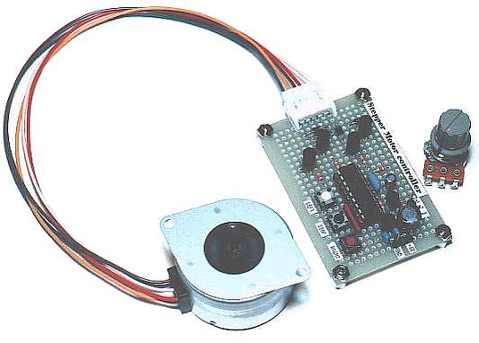
Stepper Motor controller (PIC16F84)
On these pages, I will introduce a control circuit for stepper motor.
The software of this project is adapted to Embedded Systems(Lab13) for 2002 of Cleveland State University.
Operation principle of stepper motor
On this page, I will explain about the operation principle of stepper motor.
There are many kind of stepper motors. Unipolar type, Bipolar type, Single-phase type, Multi-phase type... Single-phase stepper motor is often used for quartz watch.
On this page, I will explain the operation principle of the 2-phase unipolar PM type stepper motor.
In the PM type stepper motor, a permanent magnet is used for rotor and coils are put on stator. The stepper motor model which has 4-poles is shown in the figure on the left. In case of this motor, step angle of the rotor is 90 degrees.
As for four poles, the top and the bottom and either side are a pair.coil,
coil and
coil,
coil correspond respectively. For example,
The turn of the motor is controlled by the electric current which pours into
Clockwise control
Step angle 0 1 0 1 0° 1 0 0 1 90° 1 0 1 0 180° 0 1 1 0 270°
"0" means grounding.
Counterclockwise control
Step angle 0 1 0 1 0° 0 1 1 0 -90° 1 0 1 0 -180° 1 0 0 1 -270°
"0" means grounding.
You can find by the figure, the rotor is stable in the middle of 2 poles of stator. When one side of the stator polarity is changed, the bounce by the magnetism occurs. As a result, the direction of rotor's turn is fixed.
The characteristic of stepper motor is the angle can be correctly controlled and to be stable rotates ( It is due to the reliability of the control signal ). Moreover, because the rotor is fixed by the magnetism in the stationary condition as shown in the principle, the stationary power(Stationary torque) is large. It suits the use to make stop at some angle.
The motor which was used this time is 48 steps and the step angle is 7.5 degrees.
The way of controlling is the same as the previous example completely. It operates when controlling the electric current of
The case of the clockwise control is shown below.
The combination of
Circuit drawing of Stepper Motor controller
Pattern drawing of Stepper Motor controller
(Wiring side)
Pink line shows the external parts.
Motor driving circuit
This is the circuit which drives the coil of stepper motor. There are circuits which drive
Darlington connection-type transistor is used for the drive of the coil. As for the Darlington connection, 2 stages of transistors are connected inside in series. The "hfe" of this transistor is the multiplication of the "hfe" of each transistor inside. In case of 2SD1209K which was used this time, the hfe is over 4000. Because the ratio of the input electric current and the output current is big, the rising edge and the falling edge of the control signal can be made sharp.
The diode to be putting between the collector and the power is for the protection of the transistor. When the transistor becomes OFF from ON, the coil of the motor tries to continue to pass an electric current and generates high voltage. An electric current by this voltage is applied to the diode and the high voltage which applies over the transistor is prevented.
This is the circuit which controls the rotational speed of the motor.
TR1 becomes ON condition when RB7 becomes H level. In this condition, the electric charge of capacitor C1 flows through the transistor and the voltage of the both edges of the capacitor becomes 0 V almost.
When RB7 becomes an L level, the transistor becomes OFF condition. In this condition, the electric current flows through VR1 and R4 into capacitor C1 and the charging to the capacitor begins. The voltage of the both edges of the capacitor becomes high gradually as charging is done. As for the change of this voltage, refer to "Integration circuit".
The voltage of the capacitor is detected by RB5. The software of PIC interrupts the control of the motor until it checks RB5 after making RB7 an L level and RB5 becomes H level. When making the value of VR1 small, the charging time of the capacitor is short and the control of the motor becomes quick. The control of the motor becomes slow when making VR1 big. The speed control range can be changed by changing the value of the capacitor.
This is the circuit for the clockwise rotating, the counterclockwise rotating or stopping a motor. The baton switch of the non lock is used. Pull-up resistor is used for the port to become H level when the switch is OFF. The RB port of PIC16F84A has an internal pull up feature. However, because RB5 is used for the voltage detection of the capacitor at the circuit this time, an internal pull up feature isn't used. If using RA port for the voltage detection of the capacitor, the RB internal pull up feature can be used. The circuit this time put an external pull-up resistor in the relation of the pattern.
4-MHz resonator is used because the circuit this time doesn't need high-speed operation.
The purpose of this circuit is to keep power supply voltage to PIC to 5V when the power of the stepper motor is more than 5V.
Because the operating voltage of the stepper motor to be using this time is about 5V, the power supply voltage is +5V. In this case, the voltage which is applied to PIC becomes less than 5V because of the voltage drop (about 1V) of the regulator. In case of PIC16F84A, the operation is possible even if the power falls to about 3V because the operating voltage range is from 2V to 5.5V. It is enough in the 100-mA type.
Source code file of Stepper Motor controller
Software flow chart of Stepper Motor controller
;********************************************************
;
;               Stepper Motor controller
;
;                                 Author : Seiichi Inoue
;********************************************************

        list            p=pic16f84a
        include         p16f84a.inc
        __config _hs_osc & _wdt_off & _pwrte_on & _cp_off

;****************  Label Definition  ********************
        cblock  h'0c'
mode                            ;Operation mode
                                ;0=stop 1=right 2=left
count1                          ;Wait counter
count2                          ;Wait counter(for 1msec)
        endc

rb0     equ     0               ;RB0 of PORTB
rb1     equ     1               ;RB1 of PORTB
rb2     equ     2               ;RB2 of PORTB
rb5     equ     5               ;RB5 of PORTB
rb7     equ     7               ;RB7 of PORTB

;****************  Program Start  ***********************
        org     0               ;Reset Vector
        goto    init
        org     4               ;Interrupt Vector
        clrf    intcon          ;Clear Interruption reg

;****************  Initial Process  *********************
init
        bsf     status,rp0      ;Change to Bank1
        clrf    trisa           ;Set PORTA all OUT
        movlw   b'00100111'     ;RB0,1,2.5=IN RB7=OUT
        movwf   trisb           ;Set PORTB
        movlw   b'10000000'     ;RBPU=1 Pull up not use
        movwf   option_reg      ;Set OPTION_REG
        bcf     status,rp0      ;Change to Bank0
        clrf    mode            ;Set mode = stop
        clrf    count1          ;Clear counter
        clrf    count2          ;Clear counter
        movlw   b'00000101'     ;Set PORTA initial value
        movwf   porta           ;Write PORTA
        bsf     portb,rb7       ;Set RB7 = 1
        btfsc   portb,rb5       ;RB5 = 0 ?
        goto    $-1             ;No. Wait

start
;*************  Check switch condition  *****************
        btfsc   portb,rb1       ;RB1(stop key) = ON ?
        goto    check1          ;No. Next
        clrf    mode            ;Yes. Set stop mode
        goto    drive           ;No. Jump to motor drive
check1
        btfsc   portb,rb2       ;RB2(right key) = ON ?
        goto    check2          ;No. Next
        movlw   d'1'            ;Yes. Set right mode
        movwf   mode            ;Save mode
        goto    drive           ;No. Jump to motor drive
check2
        btfsc   portb,rb0       ;RB0(left key) = ON ?
        goto    drive           ;No. Jump to motor drive
        movlw   d'2'            ;Yes. Set left mode
        movwf   mode            ;Save mode

;********************  Motor drive  *********************
drive
        movf    mode,w          ;Read mode
        bz      start           ;mode = stop
        bsf     portb,rb7       ;Set RB7 = 1
        btfsc   portb,rb5       ;RB5 = 0 ?
        goto    $-1             ;No. Wait
        movlw   d'5'            ;Set loop count(5msec)
        movwf   count1          ;Save loop count
loop    call    timer           ;Wait 1msec
        decfsz  count1,f        ;count - 1 = 0 ?
        goto    loop            ;No. Continue
        bcf     portb,rb7       ;Set RB7 = 0
        btfss   portb,rb5       ;RB5 = 1 ?
        goto    $-1             ;No. Wait
        movf    porta,w         ;Read PORTA
        sublw   b'000000101'    ;Check motor position
        bnz     drive2          ;Unmatch
        movf    mode,w          ;Read mode
        sublw   d'1'            ;Right ?
        bz      drive1          ;Yes. Right
        movlw   b'00001001'     ;No. Set Left data
        goto    drive_end       ;Jump to PORTA write
drive1
        movlw   b'00000110'     ;Set Right data
        goto    drive_end       ;Jump to PORTA write
;-------
drive2
        movf    porta,w         ;Read PORTA
        sublw   b'000000110'    ;Check motor position
        bnz     drive4          ;Unmatch
        movf    mode,w          ;Read mode
        sublw   d'1'            ;Right ?
        bz      drive3          ;Yes. Right
        movlw   b'00000101'     ;No. Set Left data
        goto    drive_end       ;Jump to PORTA write
drive3
        movlw   b'00001010'     ;Set Right data
        goto    drive_end       ;Jump to PORTA write
;-------
drive4
        movf    porta,w         ;Read PORTA
        sublw   b'000001010'    ;Check motor position
        bnz     drive6          ;Unmatch
        movf    mode,w          ;Read mode
        sublw   d'1'            ;Right ?
        bz      drive5          ;Yes. Right
        movlw   b'00000110'     ;No. Set Left data
        goto    drive_end       ;Jump to PORTA write
drive5
        movlw   b'00001001'     ;Set Right data
        goto    drive_end       ;Jump to PORTA write
;-------
drive6
        movf    porta,w         ;Read PORTA
        sublw   b'000001001'    ;Check motor position
        bnz     drive8          ;Unmatch
        movf    mode,w          ;Read mode
        sublw   d'1'            ;Right ?
        bz      drive7          ;Yes. Right
        movlw   b'00001010'     ;No. Set Left data
        goto    drive_end       ;Jump to PORTA write
drive7
        movlw   b'00000101'     ;Set Right data
        goto    drive_end       ;Jump to PORTA write
;-------
drive8
        movlw   b'00000101'     ;Compulsion setting

drive_end
        movwf   porta           ;Write PORTA
        goto    start           ;Jump to start

;*************  1msec Timer Subroutine  *****************
timer
        movlw   d'200'          ;Set loop count
        movwf   count2          ;Save loop count
tmlp    nop                     ;Time adjust
        nop                     ;Time adjust
        decfsz  count2,f        ;count - 1 = 0 ?
        goto    tmlp            ;No. Continue
        return                  ;Yes. Count end

;********************************************************
;             END of Stepper Motor controller
;********************************************************

        end
Listing file of Stepper Motor controller
MPASM 02.50.02 Intermediate      STEP.ASM   3-9-2001  23:52:45         PAGE  1


LOC  OBJECT CODE     LINE SOURCE TEXT
  VALUE

                      00001 ;********************************************************
                      00002 ;
                      00003 ;               Stepper Motor controller
                      00004 ;
                      00005 ;                                 Author : Seiichi Inoue
                      00006 ;********************************************************
                      00007
                      00008         LIST            P=PIC16F84A
                      00009         INCLUDE         P16F84A.INC
                      00001         LIST
                      00002 ; P16F84A.INC  Standard Header File, Version 2.00'(modify)
                      00134         LIST
2007   3FF2           00010         __CONFIG _HS_OSC & _WDT_OFF & _PWRTE_ON & _CP_OFF
                      00011
                      00012 ;****************  Label Definition  ********************
                      00013         CBLOCK  H'0c'
  0000000C            00014 MODE                            ;Operation mode
                      00015                                 ;0=stop 1=right 2=left
  0000000D            00016 COUNT1                          ;Wait counter
  0000000E            00017 COUNT2                          ;Wait counter(for 1msec)
                      00018         ENDC
                      00019
  00000000            00020 RB0     EQU     0               ;RB0 of PORTB
  00000001            00021 RB1     EQU     1               ;RB1 of PORTB
  00000002            00022 RB2     EQU     2               ;RB2 of PORTB
  00000005            00023 RB5     EQU     5               ;RB5 of PORTB
  00000007            00024 RB7     EQU     7               ;RB7 of PORTB
                      00025
                      00026 ;****************  Program Start  ***********************
0000                  00027         ORG     0               ;Reset Vector
0000   2805           00028         GOTO    INIT
0004                  00029         ORG     4               ;Interrupt Vector
0004   018B           00030         CLRF    INTCON          ;Clear Interruption reg
                      00031
                      00032 ;****************  Initial Process  *********************
0005                  00033 INIT
0005   1683           00034         BSF     STATUS,RP0      ;Change to Bank1
0006   0185           00035         CLRF    TRISA           ;Set PORTA all OUT
0007   3027           00036         MOVLW   B'00100111'     ;RB0,1,2.5=IN RB7=OUT
0008   0086           00037         MOVWF   TRISB           ;Set PORTB
0009   3080           00038         MOVLW   B'10000000'     ;RBPU=1 Pull up not use
000A   0081           00039         MOVWF   OPTION_REG      ;Set OPTION_REG
000B   1283           00040         BCF     STATUS,RP0      ;Change to Bank0
000C   018C           00041         CLRF    MODE            ;Set mode = stop
000D   018D           00042         CLRF    COUNT1          ;Clear counter
000E   018E           00043         CLRF    COUNT2          ;Clear counter
000F   3005           00044         MOVLW   B'00000101'     ;Set PORTA initial value
0010   0085           00045         MOVWF   PORTA           ;Write PORTA
0011   1786           00046         BSF     PORTB,RB7       ;Set RB7 = 1
0012   1A86           00047         BTFSC   PORTB,RB5       ;RB5 = 0 ?
0013   2812           00048         GOTO    $-1             ;No. Wait
                      00049
0014                  00050 START
MPASM 02.50.02 Intermediate      STEP.ASM   3-9-2001  23:52:45         PAGE  2


LOC  OBJECT CODE     LINE SOURCE TEXT
  VALUE

                      00051 ;*************  Check switch condition  *****************
0014   1886           00052         BTFSC   PORTB,RB1       ;RB1(stop key) = ON ?
0015   2818           00053         GOTO    CHECK1          ;No. Next
0016   018C           00054         CLRF    MODE            ;Yes. Set stop mode
0017   2821           00055         GOTO    DRIVE           ;No. Jump to motor drive
0018                  00056 CHECK1
0018   1906           00057         BTFSC   PORTB,RB2       ;RB2(right key) = ON ?
0019   281D           00058         GOTO    CHECK2          ;No. Next
001A   3001           00059         MOVLW   D'1'            ;Yes. Set right mode
001B   008C           00060         MOVWF   MODE            ;Save mode
001C   2821           00061         GOTO    DRIVE           ;No. Jump to motor drive
001D                  00062 CHECK2
001D   1806           00063         BTFSC   PORTB,RB0       ;RB0(left key) = ON ?
001E   2821           00064         GOTO    DRIVE           ;No. Jump to motor drive
001F   3002           00065         MOVLW   D'2'            ;Yes. Set left mode
0020   008C           00066         MOVWF   MODE            ;Save mode
                      00067
                      00068 ;********************  Motor drive  *********************
0021                  00069 DRIVE
0021   080C           00070         MOVF    MODE,W          ;Read mode
0022   1903 2814      00071         BZ      START           ;mode = stop
0024   1786           00072         BSF     PORTB,RB7       ;Set RB7 = 1
0025   1A86           00073         BTFSC   PORTB,RB5       ;RB5 = 0 ?
0026   2825           00074         GOTO    $-1             ;No. Wait
0027   3005           00075         MOVLW   D'5'            ;Set loop count(5msec)
0028   008D           00076         MOVWF   COUNT1          ;Save loop count
0029   2062           00077 LOOP    CALL    TIMER           ;Wait 1msec
002A   0B8D           00078         DECFSZ  COUNT1,F        ;count - 1 = 0 ?
002B   2829           00079         GOTO    LOOP            ;No. Continue
002C   1386           00080         BCF     PORTB,RB7       ;Set RB7 = 0
002D   1E86           00081         BTFSS   PORTB,RB5       ;RB5 = 1 ?
002E   282D           00082         GOTO    $-1             ;No. Wait
002F   0805           00083         MOVF    PORTA,W         ;Read PORTA
0030   3C05           00084         SUBLW   B'000000101'    ;Check motor position
0031   1D03 283B      00085         BNZ     DRIVE2          ;Unmatch
0033   080C           00086         MOVF    MODE,W          ;Read mode
0034   3C01           00087         SUBLW   D'1'            ;Right ?
0035   1903 2839      00088         BZ      DRIVE1          ;Yes. Right
0037   3009           00089         MOVLW   B'00001001'     ;No. Set Left data
0038   2860           00090         GOTO    DRIVE_END       ;Jump to PORTA write
0039                  00091 DRIVE1
0039   3006           00092         MOVLW   B'00000110'     ;Set Right data
003A   2860           00093         GOTO    DRIVE_END       ;Jump to PORTA write
                      00094 ;-------
003B                  00095 DRIVE2
003B   0805           00096         MOVF    PORTA,W         ;Read PORTA
003C   3C06           00097         SUBLW   B'000000110'    ;Check motor position
003D   1D03 2847      00098         BNZ     DRIVE4          ;Unmatch
003F   080C           00099         MOVF    MODE,W          ;Read mode
0040   3C01           00100         SUBLW   D'1'            ;Right ?
0041   1903 2845      00101         BZ      DRIVE3          ;Yes. Right
0043   3005           00102         MOVLW   B'00000101'     ;No. Set Left data
0044   2860           00103         GOTO    DRIVE_END       ;Jump to PORTA write
MPASM 02.50.02 Intermediate      STEP.ASM   3-9-2001  23:52:45         PAGE  3


LOC  OBJECT CODE     LINE SOURCE TEXT
  VALUE

0045                  00104 DRIVE3
0045   300A           00105         MOVLW   B'00001010'     ;Set Right data
0046   2860           00106         GOTO    DRIVE_END       ;Jump to PORTA write
                      00107 ;-------
0047                  00108 DRIVE4
0047   0805           00109         MOVF    PORTA,W         ;Read PORTA
0048   3C0A           00110         SUBLW   B'000001010'    ;Check motor position
0049   1D03 2853      00111         BNZ     DRIVE6          ;Unmatch
004B   080C           00112         MOVF    MODE,W          ;Read mode
004C   3C01           00113         SUBLW   D'1'            ;Right ?
004D   1903 2851      00114         BZ      DRIVE5          ;Yes. Right
004F   3006           00115         MOVLW   B'00000110'     ;No. Set Left data
0050   2860           00116         GOTO    DRIVE_END       ;Jump to PORTA write
0051                  00117 DRIVE5
0051   3009           00118         MOVLW   B'00001001'     ;Set Right data
0052   2860           00119         GOTO    DRIVE_END       ;Jump to PORTA write
                      00120 ;-------
0053                  00121 DRIVE6
0053   0805           00122         MOVF    PORTA,W         ;Read PORTA
0054   3C09           00123         SUBLW   B'000001001'    ;Check motor position
0055   1D03 285F      00124         BNZ     DRIVE8          ;Unmatch
0057   080C           00125         MOVF    MODE,W          ;Read mode
0058   3C01           00126         SUBLW   D'1'            ;Right ?
0059   1903 285D      00127         BZ      DRIVE7          ;Yes. Right
005B   300A           00128         MOVLW   B'00001010'     ;No. Set Left data
005C   2860           00129         GOTO    DRIVE_END       ;Jump to PORTA write
005D                  00130 DRIVE7
005D   3005           00131         MOVLW   B'00000101'     ;Set Right data
005E   2860           00132         GOTO    DRIVE_END       ;Jump to PORTA write
                      00133 ;-------
005F                  00134 DRIVE8
005F   3005           00135         MOVLW   B'00000101'     ;Compulsion setting
                      00136
0060                  00137 DRIVE_END
0060   0085           00138         MOVWF   PORTA           ;Write PORTA
0061   2814           00139         GOTO    START           ;Jump to start
                      00140
                      00141 ;*************  1msec Timer Subroutine  *****************
0062                  00142 TIMER
0062   30C8           00143         MOVLW   D'200'          ;Set loop count
0063   008E           00144         MOVWF   COUNT2          ;Save loop count
0064   0000           00145 TMLP    NOP                     ;Time adjust
0065   0000           00146         NOP                     ;Time adjust
0066   0B8E           00147         DECFSZ  COUNT2,F        ;count - 1 = 0 ?
0067   2864           00148         GOTO    TMLP            ;No. Continue
0068   0008           00149         RETURN                  ;Yes. Count end
                      00150
                      00151 ;********************************************************
                      00152 ;             END of Stepper Motor controller
                      00153 ;********************************************************
                      00154
                      00155         END
MPASM 02.50.02 Intermediate      STEP.ASM   3-9-2001  23:52:45         PAGE  4

Label list has been deleted.


MEMORY USAGE MAP ('X' = Used,  '-' = Unused)

0000 : X---XXXXXXXXXXXX XXXXXXXXXXXXXXXX XXXXXXXXXXXXXXXX XXXXXXXXXXXXXXXX
0040 : XXXXXXXXXXXXXXXX XXXXXXXXXXXXXXXX XXXXXXXXX------- ----------------
2000 : -------X-------- ---------------- ---------------- ----------------

All other memory blocks unused.

Program Memory Words Used:   102
Program Memory Words Free:   922


Errors   :     0
Warnings :     0 reported,     0 suppressed
Messages :     0 reported,     0 suppressed